Scope API#
The scope object is used to control the capture/glitch portion of the ChipWhisperer device.
The easiest way to create a scope object is via the chipwhisperer.scope() function,
which will connect to a ChipWhisperer device and return a scope object of the correct type:
import chipwhisperer as cw
scope = cw.scope()
There are currently two types of scopes:
OpenADC Scope (Lite, Pro, Husky)
ChipWhisperer Nano Scope (Nano)
These scope objects also inherit common methods from Common Scope Attributes.
- chipwhisperer.scope(scope_type=None, name=None, sn=None, idProduct=None, bitstream=None, force=False, prog_speed=10000000, **kwargs) chipwhisperer.scope()#
Create a scope object and connect to it.
This function allows any type of scope to be created. By default, the object created is based on the attached hardware (OpenADC for CWLite/CW1200, CWNano for CWNano).
- Scope Types:
scopes.OpenADC(Pro and Lite)scopes.CWNano(Nano)
If multiple chipwhisperers are connected, the serial number of the one you want to connect to can be specified by passing sn=<SERIAL_NUMBER>
- Parameters:
scope_type (
Optional[Type[Union[OpenADC,CWNano]]]) – Scope type to connect to. Types can be found in chipwhisperer.scopes. If None, will try to detect the type of ChipWhisperer connected. Defaults to None.name (
Optional[str]) –model name of the ChipWhisperer that you want to connect to. Alternative to specifying the serial number when multiple ChipWhisperers, all of different type, are connected. Defaults to None. Valid values:
Nano
Lite
Pro
Husky
idProduct (
Optional[int]) –idProduct of the ChipWhisperer that you want to connect to. Alternative to specifying the serial number when multiple ChipWhisperers, all of different type, are connected. Defaults to None. Valid values:
0xace0: CW-Nano
0xace2: CW-Lite
0xace3: CW-Pro
0xace5: CW-Husky
sn (
Optional[str]) – Serial number of ChipWhisperer that you want to connect to. sn is required if more than one ChipWhisperer of the same type is connected (i.e. two CWNano’s or a CWLite and CWPro). Defaults to None.bitstream (
Optional[str]) – Path to bitstream to program. If None, programs default bitstream. Optional, defaults to None. Ignored on Nano.force (
bool) – If True, always erase and program FPGA. If False, only erase and program FPGA if it is currently blank. Defaults to False. Ignored on Nano.prog_speed (
int) – Sets the FPGA programming speed for Lite, Pro, and Husky. If you get programming errors, try turning this down.
- Return type:
- Returns:
Connected scope object.
- Raises:
OSError – Can be raised for issues connecting to the chipwhisperer, such as not having permission to access the USB device or no ChipWhisperer being connected.
Warning – Raised if multiple chipwhisperers are connected, but the type and/or the serial numbers are not specified
Changed in version 5.1: Added autodetection of scope_type
Changed in version 5.5: Added idProduct, name, bitstream, and force parameters.
As of ChipWhisperer 5.6.2, ChipWhisperer can find all connected devices:
- chipwhisperer.list_devices(idProduct=None, get_sn=True, get_hw_loc=True) chipwhisperer.list_devices()#
Get a list of devices by NewAE (VID 0x2b3e) currently connected
- Parameters:
idProduct (Optional[List[int]], optional) – List of PIDs to restrict devices to. If None, do not restrict. Defaults to None.
get_sn (bool, optional) – Whether or not to try to access serial number. Can fail if another process is connected or if we don’t have permission to access the device. Defaults to True.
get_hw_loc (bool, optional) – Whether or not to access the hardware location of the device. Can fail due to the same reasons as above. Defaults to True.
- Returns:
A list of dicts with fields {‘name’: str, ‘sn’, str, ‘hw_loc’: (int, int)}
- Return type:
List[dict]
If an unknown NewAE device is connected, ‘name’ will be ‘unknown’. If ‘sn’ or ‘hw_loc’ are not desired, or cannot be accessed, they will be None.
Added in version 5.6.2.
OpenADC Scope#
Supported scopes:
Usage examples:
- class chipwhisperer.scopes.OpenADC#
OpenADC scope object.
This class contains the public API for the OpenADC hardware, including the ChipWhisperer Lite/ CW1200 Pro boards. It includes specific settings for each of these devices.
To connect to one of these devices, the easiest method is:
import chipwhisperer as cw
scope = cw.scope(scope_type=cw.scopes.OpenADC)
Some sane default settings are available via:
scope.default_setup()
This code will automatically detect an attached ChipWhisperer device and connect to it.
For more help about scope settings, try help() on each of the ChipWhisperer scope submodules (scope.gain, scope.adc, scope.clock, scope.io, scope.trigger, and scope.glitch):
If you have a CW1200 ChipWhisperer Pro, you have access to some additional features:
If you have a CW-Husky, you have access to even more additional features:
Inherits from
chipwhisperer.capture.api.cwcommon.ChipWhispererCommonInterface- arm()#
Setup scope to begin capture/glitching when triggered.
The scope must be armed before capture or glitching (when set to ‘ext_single’) can begin.
- Raises:
OSError – Scope isn’t connected.
Exception – Error when arming. This method catches these and disconnects before reraising them.
- capture(poll_done=False)#
Captures trace. Scope must be armed before capturing.
Blocks until scope triggered (or times out), then disarms scope and copies data back.
Read captured data out with
scope.get_last_trace()- Parameters:
poll_done (
bool) – Supported by Husky only. Poll Husky to find out when it’s done capturing, instead of calculating the capture time based on the capture parameters. Can result in slightly faster captures when the number of samples is high. Defaults to False.- Return type:
bool- Returns:
True if capture timed out, false if it didn’t.
- Raises:
IOError – Unknown failure.
Changed in version 5.6.1: Added poll_done parameter for Husky
- capture_segmented()#
Captures trace in segment mode, returns as many segments as buffer holds.
Timeouts not handled yet properly (function will lock). Be sure you are generating enough triggers for segmented mode.
- Returns:
True if capture timed out, false if it didn’t.
- Raises:
IOError – Unknown failure.
Added in version 5.5: Added segmented capture (requires custom bitstream)
- cglitch_setup(default_setup=True)#
Sets up sane defaults for clock glitching
glitch clk_src = clkgen
output = clock_xor
trigger_src = ext_single
hs2 = glitch
LP and HP glitch disabled
- con(sn=None, idProduct=None, bitstream=None, force=False, prog_speed=10000000.0, **kwargs)#
Connects to attached chipwhisperer hardware (Lite, Pro, or Husky)
- Parameters:
sn (str) – The serial number of the attached device. Does not need to be specified unless there are multiple devices attached.
idProduct (int) – The product ID of the ChipWhisperer. If None, autodetects product ID. Optional.
bitstream (str) – Path to bitstream to program. If None, programs default bitstream. Optional.
force (bool) – Force reprogramming of bitstream. If False, only program bitstream if no bitstream is currently programmed. Optional.
- Returns:
True if connection is successful, False otherwise
Changed in version 5.5: Added idProduct, bitstream, and force parameters.
- default_setup(verbose=True, sleep=0.2)#
Sets up sane capture defaults for this scope
25dB gain
5000 capture samples
0 sample offset
rising edge trigger
7.37MHz clock output on hs2
4*7.37MHz ADC clock
tio1 = serial rx
tio2 = serial tx
tio4 = highZ
CDC settings change off
Added in version 5.1: Added default setup for OpenADC
- dis()#
Disconnects the current scope object.
- Returns:
True if the disconnection was successful, False otherwise.
- property fpga_buildtime#
When the FPGA bitfile was generated. Husky only.
- get_last_trace(as_int=False)#
Return the last trace captured with this scope.
Can return traces as floating point values (
as_int=False) or as integers.Floating point values are scaled and shifted to be between -0.5 and 0.5.
Integer values are raw readings from the ChipWhisperer ADC. The ChipWhisperer-Lite has a 10-bit ADC, the Nano has an 8-bit ADC, and the Husky can read either 8-bits or 12-bits of ADC data.
- Parameters:
as_int (
bool) – If False, return trace as a float. Otherwise, return as an int.- Return type:
ndarray- Returns:
Numpy array of the last capture trace.
Changed in version 5.6.1: Added as_int parameter
- get_last_trace_segmented()#
Return last trace assuming it was captured with segmented mode.
For CW-Lite/Pro (fifo_fill_mode=”segment”), the trigger occupies one sample slot per segment, so each returned segment is 1 sample shorter than the requested sample count.
For CW-Husky, segments use the full requested sample count.
- Returns:
2-D numpy array of the last captured traces.
Added in version 5.5: Added segmented capture (requires custom bitstream)
- get_name()#
Gets the name of the attached scope
- Returns:
‘ChipWhisperer Lite’ if a Lite, ‘ChipWhisperer Pro’ if a Pro, ‘ChipWhisperer Husky’ if a Husky
- glitch_disable()#
Disables glitch and glitch outputs
- reload_fpga(bitstream=None, reconnect=True, prog_speed=1000000.0)#
(Re)loads a FPGA bitstream (even if already configured).
Will cause a reconnect event, all settings become default again. If no bitstream specified default is used based on current configuration settings.
- Parameters:
bitstream (str or None) – Path to new bitstream file. Optional, defaults to None
reconnect (True) – Whether or not to reconnect to the scope
prog_speed (int) – Speed at which to program the FPGA
- reset_fpga()#
Reset Husky FPGA. This causes all FPGA-based settings to return to their default values.
- scope_diff(scope_dict1, scope_dict2)#
Reports differences between two sets of scope settings.
- Parameters:
scope_dict1 – dictionary of scope settings (obtained with scope._dict_repr())
scope_dict2 – dictionary of scope settings (obtained with scope._dict_repr())
- try_wait_clkgen_locked(count, delay=0)#
Tries to wait for clkgen to lock.
- Returns:
True if clkgen locked within the timeout, else False for a timeout.
- vglitch_setup(glitcht, default_setup=True)#
Sets up sane defaults for voltage glitch
glitch clk_src = clkgen
output = glitch_only
trigger_src = ext_single
hs2 = clkgen
LP glitch if glitcht = ‘lp’ or ‘both’
HP glitch if glitcht = ‘hp’ or ‘both’
scope.gain#
Class to control ADC gain.
- class chipwhisperer.capture.scopes._OpenADCInterface.GainSettings(oaiface, adc)#
- property db: float#
The gain of the ChipWhisperer’s low-noise amplifier in dB. Ranges from -6.5 dB to 56 dB, depending on the amplifier settings.
- Getter:
Return the current gain in dB (float)
- Setter:
Set the gain level in dB
- Raises:
ValueError – if new gain is outside of [-6.5, 56]
Examples:
# reading and storing
gain_db = scope.gain.db

# setting
scope.gain.db = 20
- property gain: int#
The current LNA gain setting.
This gain is a dimensionless number in the range [0, 78]. Higher value causes higher gain in dB.
Note that this function is unnecessary - the dB gain can be set directly. This property is only here to help convert old scripts.
- Getter:
Return the current gain setting (int)
- Setter:
Set the gain
- Raises:
ValueError – if gain outside [0, 78]
- property mode: str#
The current mode of the LNA.
The LNA can operate in two modes: low-gain or high-gain. Generally, the high-gain setting is better to use. Note that this value will be automatically updated if the dB gain is set.
- Getter:
Return the current gain mode (“low” or “high”)
- Setter:
Set the gain mode
- Raises:
ValueError – if mode not one of “low” or “high”
scope.adc#
Class to control non-gain, non-clock ADC settings.
- class chipwhisperer.capture.scopes._OpenADCInterface.TriggerSettings(oaiface)#
- property basic_mode: str#
The type of event to use as a trigger.
Only applies to the ADC capture - the glitch module is always a rising edge trigger.
- There are four possible types of trigger events:
“low”: triggers when line is low (logic 0)
“high”: triggers when line is high (logic 1)
“rising_edge”: triggers when line transitions from low to high
“falling_edge:” triggers when line transitions from high to low
Warning
This must be set to “rising_edge” if a trigger other than “basic” is used. The SAD/DecodeIO triggers will not work with any other setting!
- Getter:
Return the current trigger mode (one of the 4 above strings)
- Setter:
Set the trigger mode
- Raises:
ValueError – if value is not one of the allowed strings
- clear_clip_errors()#
ADC clipping errors are sticky until manually cleared by calling this.
- property clip_errors_disabled#
By default, ADC clipping is flagged as an error. Disable if you do not want this error notification.
- property decimate#
The ADC downsampling factor.
This value instructs the ChipWhisperer to only record 1 sample in every <decimate>. In other words, if this value is set to 10, the sampling rate is set to 1/10th of the sampling clock.
This setting is helpful for recording very long operations or for reducing the sampling rate for streaming mode.
- Getter:
Return an integer with the current decimation factor
- Setter:
Set the decimation factor
- Raises:
ValueError – if the new factor is not positive
- property fifo_fill_mode: str#
The ADC buffer fill strategy - allows segmented usage for CW-lite and CW-pro.
Warning
THIS REQUIRES NEW FPGA BITSTREAM - NOT YET IN THE PYTHON.
Only the ‘Normal’ mode is well supported, the other modes can be used carefully.
For segmenting on CW-Husky, see ‘segments’ instead.
- There are four possible modes:
“normal”: Trigger line & logic work as expected.
“enable”: Capture starts with rising edge, but writing samples is enabled by active-high state of trigger line.
“segment”: Capture starts with rising edge, and writes trigger.samples to buffer on each rising edge, stopping when the buffer is full. For this to work adc.samples must be a multiple of 3 (will be enforced by API).
Warning
The “enable” and “segment” modes requires you to fill the full buffer (~25K on CW-Lite, ~100K on CW-Pro). This requires you to ensure the physical trigger line will be high (enable mode) or toggle (segment mode) enough. The ChipWhisperer hardware will currently stall until the internal buffer is full, and future commands will fail.
Warning
adc.basic_mode must be set to “rising_edge” if a fill_mode other than “normal” is used. Bad things happen if not.
- Getter:
Return the current fifo fill mode (one of the 3 above strings)
- Setter:
Set the fifo fill mode
- Raises:
ValueError – if value is not one of the allowed strings
- property fifo_state#
Husky only, for debugging; state of the Husky FIFO FSM.
- property lo_gain_errors_disabled#
By default, captures which use less than a quarter of the ADC’s dynamic range flag an error, to indicate that the gain should be increased. Disable if you do not want this error notification.
- property offset#
The number of samples to wait before recording data after seeing a trigger event.
This offset is useful for long operations. For instance, if an encryption is 1 million samples long, it’s difficult to capture the entire power trace, but an offset can be used to skip to the end of the encryption.
The offset must be a 32 bit unsigned integer.
- Getter:
Return the current offset (integer)
- Setter:
Set a new offset
- Raises:
ValueError – if offset outside of range [0, 2**32)
- property presamples#
The number of samples to record from before the trigger event.
This setting must be a positive integer, and it cannot be larger than the number of samples. When streaming mode is enabled, this value is set to 0.
- Getter:
Return the current number of presamples
- Setter:
Set the number of presamples.
- Raises:
ValueError – if presamples is outside of range [0, samples]
- property samples#
The number of ADC samples to record in a single capture.
The maximum number of samples is hardware-dependent: - cwlite: 24400 - cw1200: 96000 - cwhusky: 131070
- Getter:
Return the current number of total samples (integer)
- Setter:
Set the number of samples to capture
- Raises:
ValueError – if number of samples is negative
- property state#
The current state of the trigger input.
This is a digital value (ie: high or low), which is some combination of the pins in the triggermux object. Read-only.
Getter: Return the current state (True or False).
- property timeout#
The number of seconds to wait before aborting a capture.
If no trigger event is detected before this time limit is up, the capture fails and no data is returned.
- Getter:
Return the number of seconds before a timeout (float)
- Setter:
Set the timeout in seconds
- property trig_count: int#
The number of samples that the trigger input was active.
This value indicates how long the trigger was high or low last time a trace was captured. It is the number of samples where the input was low (in “low” or “falling edge” modes) or high (in “high” or “rising edge” modes). Read-only.
This counter is not meaningful if the trigger is still active.
- Getter:
Return the last trigger duration (integer)
scope.adc (Pro/Husky Only)#
The following scope.adc members are only available on ChipWhisperer-Husky, ChipWhisperer-Pro, or both.
- class chipwhisperer.capture.scopes._OpenADCInterface.TriggerSettings(oaiface)
- property TriggerSettings.stream_mode#
The ChipWhisperer’s streaming status. Only available on CW1200 and CW-Husky.
When stream mode is enabled, the ChipWhisperer sends back ADC data as soon as it is recorded. In this mode, there is no hardware limit on the maximum number of samples per trace (although Python may run out of memory when recording billions of points). However, there is a maximum streaming data rate, which is approximately 10 Msamp/s.
Note that no pre-trigger samples can be recorded when stream mode is enabled.
- Getter:
Return True if stream mode is enabled and False otherwise
- Setter:
Enable or disable stream mode
- property TriggerSettings.segment_cycles: int#
Number of clock cycles separating segments.
Warning
Supported by CW-Husky only. For segmenting on CW-lite or CW-pro, see ‘fifo_fill_mode’ instead.
This setting must be a 20-bit positive integer.
When ‘segments’ is greater than one, set segment_cycles to a non-zero value to capture a new segment every ‘segment_cycles’ clock cycles following the initial trigger event. ‘segment_cycle_counter_en’ must also be set.
Typically, segment_cycles should be much greater than scope.adc.samples. If they are too close, capture will fail (indicated by the blinking red lights and scope.adc.errors showing either a segmenting error or a FIFO over/underflow error).
When presamples = 0, segment_cycles >= samples + 10.
When presamples > 0, segment_cycles >= samples + presamples AND segment_cycles >= samples + 10.
- Getter:
Return the current value of segment_cycles.
- Setter:
Set segment_cycles.
- Raises:
ValueError – if segments is outside of range [0, 2^20-1]
- property TriggerSettings.segment_cycle_counter_en: bool#
Number of clock cycles separating segments.
Warning
Supported by CW-Husky only. For segmenting on CW-lite or CW-pro, see ‘fifo_fill_mode’ instead.
Set to 0 to capture a new power trace segment every time the target issues a trigger event.
Set to 1 to capture a new power trace segment every ‘segment_cycles’ clock cycles after a single trigger event.
- Getter:
Return the current value of segment_cycle_counter_en.
- Setter:
Set segment_cycles.
- property TriggerSettings.first_error_state: str#
Reports the state the FPGA FSM state at the time of the first flagged error. Useful for debugging. Read-only.
Warning
Supported by CW-Husky only.
- Getter:
Return the error flags.
- property TriggerSettings.errors: str | bool | int#
Internal error flags (FPGA FIFO over/underflow)
Warning
Supported by CW-Husky only.
- Error types and their causes:
‘presample error’: capture trigger occurs before the requested number of presamples have been collected. Reduce scope.adc.presamples or delay the capture trigger.
‘ADC clipped’: gain is too high; reduce it (scope.gain) or disable this error (scope.adc.clip_errors_disabled).
‘gain too low error’: gain is “too low” (4 bits or more of the ADC’s dynamic range did not get used); increase it (scope.gain) or disable this error (scope.adc.lo_gain_errors_disabled).
‘invalid downsample setting’: using downsampling (aka decimating) with presamples and multiple segments is not allowed.
‘segmenting error’: the condition for starting the capture of the next segment came true before the capture of the current segment completed. Reduce the segment size and/or increase the time between segments.
‘fast FIFO underflow’: shouldn’t occur in isolation without other errors being flagged.
‘fast FIFO overflow’: data is coming in fast than it’s being read; reduce scope.clock.adc_freq.
‘slow FIFO underflow’: host tried to read more ADC samples than are available.
‘slow FIFO overflow’: data is coming in faster than it’s being read; reduce scope.clock.adc_freq.
To fully understand the four different FIFO errors (fast/slow over/underflows), some background on Husky’s sample storage architecture is required. ADC samples are first stored in a “fast” FIFO which runs at the ADC sampling rate, then moved to a wider and “slower” FIFO which is read by the host. Overflows or underflows can occur in either FIFO. Errors can be caused from an illegal configuration of scope.adc (e.g. too many samples), or attempting to stream too fast.
- Getter:
Return the error flags.
- Setter:
Clear error flags.
- property TriggerSettings.segments: int#
Number of sample segments to capture.
Warning
Supported by CW-Husky only. For segmenting on CW-lite or CW-pro, see ‘fifo_fill_mode’ instead.
This setting must be a 16-bit positive integer.
In normal operation, segments=1.
Multiple segments are useful in two scenarios:
Capturing only subsections of a power trace, to allow longer effective captures. After a trigger event, the requested number of samples is captured every ‘segment_cycles’ clock cycles, ‘segments’ times. Set ‘segment_cycle_counter_en’ to 1 for this segment mode.
Speeding up capture times by capturing ‘segments’ power traces from a single arm + capture event. Here, the requested number of samples is captured at every trigger event, without having to re-arm and download trace data between every trigger event. Set ‘segment_cycle_counter_en’ to 0 for this segment mode.
Warning
when capturing multiple segments with presamples, the total number of samples per segment must be a multiple of 3. Incorrect sample data will be obtained if this is not the case.
- Getter:
Return the current number of presamples
- Setter:
Set the number of presamples.
- Raises:
ValueError – if segments is outside of range [1, 2^16-1]
- property TriggerSettings.bits_per_sample: int#
Bits per ADC sample. Only available on CW-Husky.
Husky has a 12-bit ADC; optionally, we read back only 8 bits per sample. This does not allow for more samples to be collected; it only allows for a faster sampling rate in streaming mode.
- Getter:
return the number of bits per sample that will be received.
- Setter:
set the number of bits per sample to receive.
scope.clock#
scope.clock (Lite/Pro Only)#
Warning
ChipWhisperer-Lite/Pro only. See
scope.clock (Husky) for Husky clock documentation.
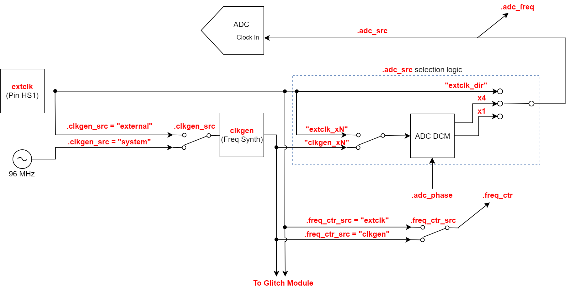
Class to control target/ADC clocks. A block diagram of the clock module is shown below:
- class chipwhisperer.capture.scopes._OpenADCInterface.ClockSettings(oaiface, hwinfo=None, is_husky=False)#
- property adc_freq: int#
The current frequency of the ADC clock in Hz. Read-only.
This clock frequency is derived from one of the ADC clock sources as described in adc_src.
- Getter:
Return the current frequency in Hz (int). May take up to 0.5s to stabilize after adc_locked is True.
- property adc_locked: bool#
The current status of the ADC DCM. Read-only.
To try re-locking the ADC, see reset_adc().
- Getter:
Return whether the ADC DCM is locked (True or False)
- property adc_mul: int#
Sets a new ADC clock frequency by multiplying this value by clkgen_freq
On Husky, must be a positive integer, or 0. If 0, turns the ADC clock off.
On Lite/Pro, must be either 1 or 4
adc_freq = adc_mul * clkgen_freq
Note that the value of adc_mul affects how closely clkgen_freq can be matched to the requested frequency. See clkgen_freq for more information.
- Getter:
The currently set adc multiplier
- Setter:
Set the adc multiplier
Changed in version 6.0: Added ChipWhisperer-Lite/Pro version of this property
- property adc_phase: int#
Fine adjustment for the ADC sampling point.
This setting moves the sampling point approximately 5 ns forward or backward, regardless of the sampling frequency. It may be helpful to improve the stability of the measurement.
The value of this setting is dimensionless and has a non-linear effect on the phase adjustment.
- Getter:
Return the current phase setting (integer) NOTE: This getter is currently broken due to an FPGA bug.
- Setter:
Set a new phase offset
- Raises:
ValueError – if offset not in [-255, 255]
TypeError – if offset not integer
- property adc_rate: int#
The current sampling rate of the ADC clock in samples/s. Read-only.
Note that the sampling rate may be less than the clock frequency if the downsampling factor is greater than 1.
- Getter:
Return the current sampling rate in samples/s (float)
- property adc_src: str#
The clock source for the ADC module.
The ADC can be clocked by one of five possible sources:
“clkgen_x1”: CLKGEN output via DCM
“clkgen_x4”: CLKGEN output via DCM with x4 clk multiplier
“extclk_x1”: External clock input via DCM
“extclk_x4”: External clock input via DCM with x4 clk multiplier
“extclk_dir”: External clock input with no DCM
- Getter:
Return the current ADC clock source (one of five strings above)
- Setter:
Set the ADC clock source and reset the ADC DCM to lock it.
- Raises:
ValueError – if string not in valid settings
- property clkgen_div: int#
The divider in the CLKGEN DCM.
This divider must be in the range [1, 256].
- Getter:
Return the current CLKGEN divider (integer)
- Setter:
Set a new CLKGEN divider.
- property clkgen_freq: str#
The CLKGEN output frequency in Hz.
The CLKGEN module takes the input source and multiplies/divides it to get a faster or slower clock as desired. Minimum clock in practice is 3.2MHz.
- Getter:
Return the current calculated CLKGEN output frequency in Hz (float). Note that this is the theoretical frequency - use the freq counter to determine the actual output. May take up to 0.5s to stabilize after clkgen_locked is True.
- Setter:
Attempt to set a new CLKGEN frequency in Hz. When this value is set, all possible DCM multiply/divide settings are tested to find which is closest to the desired output speed. If EXTCLK is the CLKGEN source, the EXTCLK frequency must be properly set for this to work. Also, both DCMs are reset.
- property clkgen_locked: bool#
The current status of the CLKGEN DCM. Read-only.
- Getter:
Return whether the CLKGEN DCM is locked (True or False)
- property clkgen_mul: int#
The multiplier in the CLKGEN DCM.
This multiplier must be in the range [2, 256].
- Getter:
Return the current CLKGEN multiplier (integer)
- Setter:
Set a new CLKGEN multiplier.
- property clkgen_src: str#
The input source for the CLKGEN DCM.
This DCM can receive input from one of two places:
“extclk”: The external clock input
“system” or “internal”: The system clock (96 MHz)
- Getter:
Return the current CLKGEN input (either “extclk” or “system”)
- Setter:
Change the CLKGEN source and reset all the DCMs.
- Raises:
ValueError – if source is not one of three strings above
- property extclk_freq: int#
The input frequency from the EXTCLK source in Hz.
This value is used to help calculate the correct CLKGEN settings to obtain a desired output frequency when using EXTCLK as CLKGEN input. It is not a frequency counter - it is only helpful if the EXTCLK frequency is already known.
- Getter:
Return the last set EXTCLK frequency in MHz (int)
- Setter:
Update the EXTCLK frequency
- property freq_ctr: int#
The current frequency at the frequency counter in Hz. Read-only.
The frequency counter can be used to check the speed of the CLKGEN output or the EXTCLK input. This value shows the current frequency reading.
- Getter:
Return the current frequency in Hz (int)
- property freq_ctr_src: str#
The current input to the frequency counter.
There are two possible inputs to the frequency counter: - “clkgen”: The CLKGEN DCM output - “extclk”: The external input clock signal
- Getter:
Return the frequency counter input (one of the above strings)
- Setter:
Set the frequency counter source
- Raises:
ValueError – if source is not “clkgen” or “extclk”
- reset_adc()#
Reset the ADC DCM.
After changing frequencies, the ADC DCM may become unlocked from its input signal. This function resets the DCM to re-lock it.
If the DCM is still unlocked after calling this function, the clock may be too fast for the ADC.
- Return type:
None
- reset_clkgen()#
Reset the CLKGEN DCM.
After changing frequencies or input sources, the CLKGEN DCM may not be locked. This function resets the DCM to re-lock it.
If the DCM is still unlocked after calling this function, the clock may be too fast for the CLKGEN module.
- Return type:
None
- reset_dcms()#
Reset the CLKGEN DCM, then the ADC DCM.
This order is necessary because the ADC may depend on having a locked clock from the CLKGEN output.
- Return type:
None
scope.clock (Husky Only)#
- class chipwhisperer.capture.scopes.cwhardware.ChipWhispererHuskyClock.ChipWhispererHuskyClock(oaiface, fpga_clk_settings, mmcm1, mmcm2, adc)#
- property adc_freq#
Calculates the ADC frequency based on clkgen_freq and adc_mul
Read-only
- property adc_locked#
Convenience function for backwards compatibility with how ADC clocks are managed on CW-lite and CW-pro.
- property adc_mul#
Sets a new ADC clock frequency by multiplying this value by clkgen_freq
Must be a positive integer, or 0. If 0, turns the ADC clock off.
adc_freq = adc_mul * clkgen_freq
Note that the value of adc_mul affects how closely clkgen_freq can be matched to the requested frequency. See clkgen_freq for more information.
- Getter:
The currently set adc multiplier
- Setter:
Set the adc multiplier
- property adc_phase: int#
Changes the phase of the ADC clock relative to the target clock. Expressed in percentage of the ADC clock period (100.0: one full clock period.
Positive values delay the ADC clock compared to the target clock and vice versa.
Negative values are not possible when scope.clock.clkgen_src is ‘extclk’.
Note: The actual phase is a 6 bit signed value, which can be set via scope.clock.adc_phase_raw. The maximum phase depends on internal PLL settings (which are dependent on the target and ADC clock frequencies), and is given by scope.clock.pll.max_phase_percent. The phase step size is scope.clock.pll.adc_phase_step_size.
Warning: under some conditions, the phase may not be consistent (i.e. vary from run to run of a notebook), or it may have a frequency-dependent offset. The conditions which lead to this are flagged as warnings when scope.clock properties are set.
- Getter:
Gets the current adc_phase.
- Setter:
Sets the adc_phase.
- property adc_phase_raw: int#
Changes the phase of the ADC clock relative to the target clock by specifying the raw PLL phase setting (chX_sync_delay register field of the the CDCI6214 PLL). The phase step size is scope.clock.pll.adc_phase_step_size.
Allowed range is [-31, 31].
Positive values delay the ADC clock compared to the target clock and vice versa.
Negative values are not possible when scope.clock.clkgen_src is ‘extclk’.
- Getter:
Gets the current raw adc_phase.
- Setter:
Sets the raw adc_phase.
- property adc_phase_step_size: float#
adc_phase_raw step size, in picoseconds.
- property adc_rate#
The current sampling rate of the ADC clock in samples/s. Read-only.
Note that the sampling rate may be less than the clock frequency if the downsampling factor is greater than 1.
- Getter:
Return the current sampling rate in samples/s (float)
- property adc_src#
Convenience function for backwards compatibility with how ADC clocks are set on CW-lite and CW-pro.
The ADC can be clocked by one of five possible sources:
“clkgen_x1”: CLKGEN output via DCM
“clkgen_x4”: CLKGEN output via DCM with x4 clk multiplier
“extclk_x1”: External clock input via DCM
“extclk_x4”: External clock input via DCM with x4 clk multiplier
“extclk_dir”: External clock input with no DCM
- Getter:
Return the current ADC clock source (one of five strings above)
- Setter:
Set the ADC clock source and reset the ADC DCM to lock it.
- Raises:
ValueError – if string not in valid settings
- clear_adc_unlock()#
Use this to decorate methods that can cause the PLL to momentarily unlock. Clears the unlock status and then re-enables it. If PLL lock is regained, then the user will see the ADC LED turn on for a short time. If the PLL remains unlocked, then the ADC LED will turn on, flicker off, then turn back on and stay on. We do this because the ADC LED is sticky (i.e. stays on after an unlock event, even when the PLL re-locks, until manually cleared).
- property clkgen_freq#
The target clock frequency in Hz.
If set to 0, turns both the target and ADC clocks off.
Some important notes for setting this value:
The minimum output frequency is 5MHz.
The maximum is 200MHz (Husky) or 250MHz (Husky Plus); exceeding this violates the maximum frequency allowed by both the FPGA and the ADC.
You may not get exactly the requested frequency. Husky gets as close as possible to the requested frequency, and a warning is issued if the generated clock differs from the requested clock by more than scope.clock.pll._freq_warning_limit (which defaults to 0.2%). Whether you get the requested frequency depends on both the requested frequency itself and adc_mul.
- Getter:
Return the calculated target clock frequency in Hz
- Setter:
Attempt to set a new target clock frequency in Hz. This also blindly clears extclk_error if there is one, but it only assumes, and does not verify, that the frequency has been updated to the correct value.
- property clkgen_locked#
Checks if the Husky PLL is locked
- property clkgen_src#
The input for the Husky’s PLL, which generates clocks for the target and the ADC.
The PLL can receive input from two places:
“system” or “internal”: An onboard crystal
“extclk”: An external clock (e.g. generated by the target).
When clkgen_src is set to “extclk”, the external clock frequency is measured to set the ADC clock accordingly. If the external clock frequency is later modified, then clkgen_src must be re-set to “extclk” in order for the frequency change to be recognized. Otherwise, the ADC sampling clock will remain tied to the previous external clock frequency.
A variant on “extclk” is “extclk_aux_io”, when the external clock is supplied on the AUX I/O MCX instead of the HS1 pin (scope.io.aux_io_mcx must be set to “high_z” in this case).
- Getter:
Return the current PLL input (“system”, “extclk” or “extclk_aux_io”)
- Setter:
Change the CLKGEN source
- Raises:
ValueError – if source is not one of the above
- property extclk_error#
When the external clock is used, a change in clock frequency exceeding extclk_error will flag an error. The purpose of this is to remind you that you need to set scope.clock.clkgen_freq to the frequency of your external clock.
- Getter:
Whether the external clock monitor has flagged an error.
- Setter:
Clear the error.
- property extclk_monitor_enabled#
When enabled, any change in the external clock frequency input exceeding the amount set in self.extclk_tolerance will trigger an error.
When using an external clock to drive ChipWhisperer (i.e. self.clkgen_src == ‘extclk’), Husky must know the frequency of that clock (by setting scope.clock.clkgen_freq). This clock monitor is a convenience to flag when the frequency changes without Husky being informed of that change.
- Getter:
Whether the external clock monitor is enabled.
- Setter:
Enable/disable the external clock monitor.
- property extclk_tolerance#
Tolerance for external clock frequency change, measured in Hz. If the difference between consecutive measurements exceeds this, an error is flagged. Defaults to ~100 Hz.
- Getter:
Get the frequency change tolerance [Hz].
- Setter:
Set the frequency change tolerance [Hz].
- property fpga_vco_freq#
Set the FPGA clock glitch PLL’s VCO frequency.
Affects
scope.glitch.phase_shift_stepsAllowed range: 600 - 1200 MHz.
- Getter:
Calculate vco from last set value [Hz]
- Setter:
Set the vco frequency [Hz]
- Raises:
ValueError – set vco out of valid range
- property freq_ctr#
Reads the frequency of the external input clock.
Caution
The clock must be present for this to function; if there is no clock, this will not return 0.
- property freq_ctr_src#
The current input to the frequency counter.
There are two possible inputs to the frequency counter: - “clkgen”: The CLKGEN DCM output - “extclk”: The external input clock signal
- Getter:
Return the frequency counter input (one of the above strings)
- Setter:
Set the frequency counter source
- Raises:
ValueError – if source is not “pll” or “extclk”
scope.io#
Module to control IO pins.
- class chipwhisperer.capture.scopes.cwhardware.ChipWhispererExtra.GPIOSettings(cwextra)#
- property aux_io_mcx: str#
Set the function of the AUX I/O MCX on Husky.
Options:
“high_z”: input: to use as a trigger (scope.trigger.triggers = ‘aux’) or clock (scope.clock.clkgen_src = ‘extclk_aux_io’).
“userio_ck”: output: provide the same clock that’s on USERIO CK.
“hs2”: output: provide the same clock that’s on HS2.
- property cdc_settings: list | None#
Check or set whether USART settings can be changed via the USB CDC connection
i.e. whether you can change USART settings (baud rate, 8n1) via a serial client like PuTTY
- Getter:
A list of length four for four possible CDC serial ports (though only one is used)
- Setter:
Can set either via an integer (which sets both ports) or an array of length 4 (which sets each port)
Returns None if using firmware before the CDC port was added
- property extclk_src: str#
The clock signal being used as input for EXTCLK.
Currently, this can only be HS1, which is the clock from the target. As such, this value is read-only.
- property glitch_hp: bool#
Whether the high-power crowbar MOSFET is enabled.
The glitch output is an SMA-connected output line that is normally connected to a target’s power rails. If this setting is enabled, a high-powered MOSFET shorts the power-rail to ground when the glitch module’s output is active.
Can be more effective than
glitch_lpfor power-hungry targets.Warning
Use with caution - ensure that the glitch module is properly configured before enabling this setting, as it is possible to permanently damage hardware with this output.
- Getter:
Return True if enabled or False if disabled
- Setter:
Turn the high-power MOSFET on or off
- property glitch_lp#
Whether the low-power crowbar MOSFET is enabled.
This is the low-power version of
glitch_hp.Has a faster response than
glitch_hp.Warning
Use with caution - ensure that the glitch module is properly configured before enabling this setting, as it is possible to permanently damage hardware with this output.
- property glitch_trig_mcx: str#
Set the function of the Trigger/Glitch Out MCX on Husky. Options:
“glitch”: glitch output (clock or voltage glitch signal, as defined by scope.glitch settings)
“trigger”: internal trigger signal (as defined by scope.trigger)
“inverted [glitch | trigger]”: inverted glitch or trigger signal
- property hs2: str | None#
The clock signal routed to the HS2 high speed output pin.
Allowed clock signals are:
“clkgen”: The output from the CLKGEN module
“glitch”: The output from the glitch module
“disabled” / None: No clock; output driven low
- Getter:
Return one of “clkgen”, “glitch”, or “disabled”
- Setter:
Set the clock to be output on HS2.
Raises: ValueError: if new value not listed above
- property husky_soft_poweron#
Sets the target soft power-on PWM parameters. When the target is powered on (when
target_pwrgoes fromFalsetoTrue), the target power on the 20-pin connector +3.3V pin doesn’t simply go from 0V to 3.3V; instead, a series of pulses is applied, so that the 3.3V line goes up gently with minimal overshoot. Without this, a target’s sudden power draw can cause Husky’s VCC lines to go out of their recommended operating ranges, which triggersscope.XADCerrors and everything that this entails (some Husky logic gets shutdown as a protective measure; refer toscope.XADCfor details).The soft power-on parameters are tuned for NewAE targets. If you use a different target, you may need to tweak these parameters in order to get a smooth, error-free target power-on.
Warning
Inappropriate values can result in
scope.XADCalarms firing when the target is powered on.- Parameters:
settings –
list of three parameters as follows:
pwm_cycles: 8-bit int, number of PWM periods in the soft power-on
pwm_period: 16-bit int, number of 96 MHz clock cycles in one PWM period
pwm_off_time: 16-bit int, number of clock cycles in one PWM period where power is off
The soft power-on sequence lasts pwm_cycles * pwm_period cycles of the 96 MHz USB clock. To better understand, consider this example (these are not necessarily good values!):
pwm_period = 100
pwm_cycles = 50
pwm_off_time = 90
When the target is powered on, power is then applied as follows:
first 90 cycles (pwm_off_time): power is off
next 10 cycles (pwm_period - pwm_off_time): power is ON
repeat steps 1 and 2 50 (pwm_cycles) times
keep power ON
The default values are as follows:
pwm_period = 2000
pwm_cycles = 35
pwm_off_time = 1995
- property miso_state: bool#
Reads the logic level of the MISO pin. Supported by Husky only.
- property mosi_state: bool#
Reads the logic level of the MOSI pin. Supported by Husky only.
- property nrst: str#
The state of the NRST pin.
See pdic for more information. See also
nrst_drive_powerofffor behaviour withtarget_pwr.
- property nrst_drive_poweroff: bool#
Control how the nRST pin is driven when
target_pwris False. If set, nRST is driven (or not) as pernrst(i.e.target_pwrhas no effect on how nRST is driven). Otherwise, nRST is tristated.Note
Our target boards pull up nRST to target_pwr; if
nrst_drive_poweroffis False and nRST is driven low, then settingtarget_pwrto False will cause nRST to pulse as it gets tristated and pulled up for a brief moment until the target power gets sufficiently low to return it to low.
- property nrst_state: bool#
Reads the logic level of the nRST pin. Supported by Husky only.
- property pdic: str#
The function of the PDIC pin output pin.
This is a GPIO pin. The following values are allowed:
“high” / True: logic 1
“low” / False: logic 0
“disabled” / “default” / “high_z” / None: undriven
- Getter:
Return one of “high”, “low”, or “high_z”. This shows how ChipWhisperer is driving this pin; it does not show its actual logic level.
- Setter:
Set the pin’s state
Raises: ValueError: if new state not listed above
- property pdic_state: bool#
Reads the logic level of the PDIC pin. Supported by Husky only.
- property pdid: str#
The state of the PDID pin.
See pdic for more information.
- property pdid_state: bool#
Reads the logic level of the PDID pin. Supported by Husky only.
- property sck_state: bool#
Reads the logic level of the SCK pin. Supported by Husky only.
- property target_pwr: bool#
Whether the target board is powered by the ChipWhisperer.
If True, the ChipWhisperer is currently supplying power to the target board; if False, it is not. This setting can be used to cycle power to the target or to help program it.
If the target board is powered through an external supply, this setting may have no effect.
Note
Setting this value to False/0 also sets the following to high-z until power is reenabled: TIO1-4, HS2, PDID, PDIC, MOSI, SCK. nRST is also tristated if
nrst_drive_poweroffis False.- Getter:
Return the current power state of the target (True or False)
- Setter:
Turn the target power on or off.
- property tio1: str#
The function of the Target IO1 pin.
TIO1 can be used for the following functions:
“serial_rx”: UART input
“serial_tx”: UART output
“high_z” / None: High impedance input
“gpio_low” / False: Driven output: logic 0
“gpio_high” / True: Driven output: logic 1
“gpio_disabled”: Driven output: no effect
For Husky, TIO1 can also be used as the
scope.bitbangerdata or clock pin; however, that cannot be set by this property; usescope.bitbanger.data_pinorscope.bitbanger.clock_pinto make this choice.Default value is “serial_rx”.
- Getter:
Return one of the above strings. This shows how ChipWhisperer is driving this pin; it does not show its actual logic level. Use scope.io.tio_states to see the actual logic level.
- Setter:
Set the Target IO1 mode.
- Raises:
ValueError – if new value is not one of the above modes
- property tio2: str#
The function of the Target IO2 pin.
TIO2 can be used for the following functions:
“serial_rx”: UART input
“serial_tx”: UART output
“high_z” / None: High impedance input
“gpio_low” / False: Driven output: logic 0
“gpio_high” / True: Driven output: logic 1
“gpio_disabled”: Driven output: no effect
For Husky, TIO2 can also be used as the
scope.bitbangerdata or clock pin; however, that cannot be set by this property; usescope.bitbanger.data_pinorscope.bitbanger.clock_pinto make this choice.Default value is “serial_tx”.
- Getter:
Return one of the above strings. This shows how ChipWhisperer is driving this pin; it does not show its actual logic level. Use scope.io.tio_states to see the actual logic level.
- Setter:
Set the Target IO2 mode.
- Raises:
ValueError – if new value is not one of the above modes
- property tio3: str#
The function of the Target IO3 pin.
TIO3 can be used for the following functions:
“serial_rx”: UART input
“serial_tx”: UART output
“high_z” / None: High impedance input
“gpio_low” / False: Driven output: logic 0
“gpio_high” / True: Driven output: logic 1
“gpio_disabled”: Driven output: no effect
For Husky, TIO3 can also be used as the
scope.bitbangerdata or clock pin; however, that cannot be set by this property; usescope.bitbanger.data_pinorscope.bitbanger.clock_pinto make this choice.Default value is “high_z”.
- Getter:
Return one of the above strings. This shows how ChipWhisperer is driving this pin; it does not show its actual logic level. Use scope.io.tio_states to see the actual logic level.
- Setter:
Set the Target IO3 mode.
- Raises:
ValueError – if new value is not one of the above modes
- property tio4: str#
The function of the Target IO4 pin.
TIO4 can be used for the following functions:
“serial_tx”: UART output
“high_z” / None: High impedance input
“gpio_low” / False: Driven output: logic 0
“gpio_high” / True: Driven output: logic 1
“gpio_disabled”: Driven output: no effect
For Husky, TIO4 can also be used as the
scope.bitbangerdata or clock pin; however, that cannot be set by this property; usescope.bitbanger.data_pinorscope.bitbanger.clock_pinto make this choice.Default value is “high_z”. Typically, this pin is used as a trigger input.
- Getter:
Return one of the above strings. This shows how ChipWhisperer is driving this pin; it does not show its actual logic level. Use scope.io.tio_states to see the actual logic level.
- Setter:
Set the Target IO4 mode
- Raises:
ValueError – if new value is not one of the above modes
- property tio_states: tuple#
Reads the logic level of the TIO pins (1-4) and returns them as a tuple of the logic levels.
Warning
ChipWhisperer firmware before release 5.2.1 does not support reading the TIO pins!
- Getter:
Read TIO states
- Returns:
A tuple of 1’s and 0’s representing the logic levels of each TIO pin
Added in version 5.3: Add documented interface for the old method of reading TIO pins
- property vcc_glitcht: int#
Gets a bitmask indicating which VCC glitch MOSFET’s are enabled, based on the VCC_GLITCHT_* consts.
- Returns:
A bitmask with the VCC_GLITCHT_HP/LP set if enabled.
- vglitch_disable()#
Disables both glitch mosfets.
- vglitch_reset(delay=0.005)#
Disables and reenables the glitch mosfets that were previously enabled.
scope.trigger#
Basic trigger control module.
- class chipwhisperer.capture.scopes.cwhardware.ChipWhispererExtra.TriggerSettings(cwextra)#
- property module#
The trigger module in use.
The trigger modules available depend on the hardware. On the CWLite, only the basic trigger module can be used; on the CW1200, the serial data and SAD triggers are available too.
Available trigger modules:
‘basic’: Trigger on a logic level or edge
- Getter:
Returns ‘basic’
- property triggers#
The logical input into the trigger module.
The trigger module uses some combination of the scope’s I/O pins to produce a single value, which it uses for edge/level detection or UART triggers. This trigger output can combine 5 pins using one of 3 different boolean operations. N/A for ‘trace’ trigger module (see scope.trace.trace_mode for how to connect trace pins.)
Pins:
tio1-4: Target I/O pins 1-4. Note that these pins can be in any mode.
nRST: Target I/O pin nRST. Note that these pins can be in any mode.
sma: An auxiliary SMA input, if available (only on CW1200)
Boolean operations:
OR: True if any inputs are True; False if none are
AND: True if all inputs are True; False if any are not
NAND: False if all inputs are True; True if any are not
Note that only one boolean operation can be used over all input pins.
Examples of acceptable trigger inputs:
“tio1”
“tio3 OR tio4”
“tio1 NAND tio2 NAND sma”
“nrst”
Examples of unallowed trigger inputs:
“tio1 tio2”
“tio1 AND tio2 OR tio3”
“tio1 OR tio1”
“tio1 XOR tio2”
“serial-tx”
- Getter:
Return a string describing the trigger mode (see examples)
- Setter:
Set the trigger mode using a string like the ones above
- Raises:
ValueError – if string cannot be converted to a legal mode
scope.trigger (Pro Only)#
- class chipwhisperer.capture.scopes.cwhardware.ChipWhispererExtra.ProTrigger(cwextra)#
- property aux_out#
Controls AUX out on the CWPro
CWPro only
- Getter:
Returns True for ‘trigger’, ‘glitch’ for ‘glitch’, ‘clock’ for ‘clock’ or False for no output.
- Setter:
Set False or 0 to disable, True or
'trigger'for trig_out,'glitch'for glitch out, or'clock'for clock_out
- property module#
The trigger module in use.
The trigger modules available depend on the hardware. On the CWLite, only the basic trigger module can be used; on the CW1200, the serial data and SAD triggers are available too.
Available trigger modules:
‘basic’: Trigger on a logic level or edge
‘SAD’: Trigger from SAD module (CWPro only)
‘DECODEIO’: Trigger from decode_IO module (CWPro only)
- Getter:
Return the active trigger module
- Setter:
Sets the active trigger module
- Raises:
ValueError – module isn’t one of the available strings
scope.trigger (Husky Only)#
- class chipwhisperer.capture.scopes.cwhardware.ChipWhispererExtra.HuskyTrigger(cwextra)#
Husky trigger object. Communicates with all the trigger modules inside CW-Husky. Usage depends on the active trigger module.
- property edges#
For triggering on edge counts, when
scope.trigger.module = 'edge_counter'.Sets the number of rising+falling edges on
scope.trigger.triggersthat need to be seen for a trigger to be issued.Edges are sampled by the ADC sampling clock (
scope.clock.adc_freq); consecutive edges must be at least 1/scope.clock.adc_freqseconds apart in order to be “seen” (and to be safe, twice that).- Parameters:
val (int) – number of edges, non-zero 16-bit integer.
- property edges_seen#
Returns the number of edges seen.
Under normal operation this should be the same as
scope.trigger.edges. When trigger generation failed, Can be useful to understand why. Resets uponscope.arm().
- get_trigger_times()#
Retrieve the timestamped trigger times.
When multiple triggers occur, the number of ADC clock cycles between successive triggers is recorded. Up to 1024 triggers can be timestamped. The counter for each timestamp is 32-bits wide; overflows are noted. Recorded triggers are automatically reset when the scope is armed.
- property level#
For triggering on ADC sample exceeding a treshold, when scope.trigger.module = ‘ADC’.
Sets the trigger threshold, in the range [-0.5, 0.5].
If positive, triggers when the ADC sample exceeds this setting; if negative, triggers when the ADC sample is below this setting.
Only a single trigger is issued (i.e. multiple samples exceeding the threshold do not each generate a trigger; cannot be used in conjunction with segmented capture).
- property max_sequenced_triggers#
Maximum number of triggers in the trigger sequence.
- property module#
The trigger module in use.
The trigger modules available depend on the hardware. On the CWLite, only the basic trigger module can be used; on the CW1200, the serial data and SAD triggers are available too.
Available trigger modules:
‘basic’: Trigger on a logic level or edge
‘ADC’: Trigger on ADC sample exceeding a threshold
‘SAD’: Trigger from SAD module
‘UART’: Trigger from UART module
‘edge_counter’: Trigger after a number of rising/falling edges
‘trace’: Trigger from TraceWhisperer
‘bitbanger’: Trigger from bitbanger module
- Getter:
Return the active trigger module
- Setter:
Sets the active trigger module
- Raises:
ValueError – module isn’t one of the available strings
- property num_triggers#
Number of triggers in the trigger sequence.
- property sad_always_active#
Make the SAD trigger module always active. Its associated trigger window will still be used: only SAD triggers inside its window will be recognized as part of the trigger sequence, but setting this allows the SAD module to fire outside of its window, which can be helpful in tuning SAD parameters.
- property sequencer_enabled#
Enable the trigger sequencer.
- property window_end#
Maximum number of clock cycles (of the ADC sampling clock) that can follow trigger #0 before trigger #1 is allowed to complete the sequence. 0 = no limit.
- Parameters:
end – 16-bit integer
- property window_start#
Minimum number of clock cycles (of the ADC sampling clock) that must follow trigger #0 before trigger #1 is allowed to complete the sequence. 0 = no limit.
- Parameters:
start – 16-bit integer
scope.glitch#
Module to control glitching. A block diagram of the module is shown below:
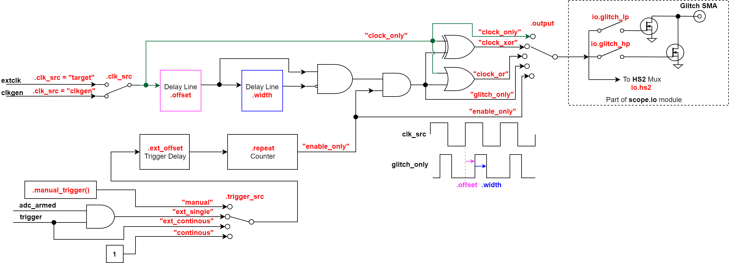
Note
This diagram is slightly inaccurate because the “offset” parameter also affects the glitch output in “enable_only” mode.
scope.glitch controls the shape of the glitch for both voltage and
clock glitching. Whether this glitch goes out into the outside world as a
voltage glitch or a clock glitch depends on scope.io
settings (as illustrated by the figure above).
This also means that some scope.glitch settings are sensible for voltage
glitching but not clock glitching, or vice-versa.
Take the time to go through our glitch notebooks to learn how to glitch with your ChipWhisperer device.
- class chipwhisperer.capture.scopes.cwhardware.ChipWhispererGlitch.GlitchSettings(cwglitch)#
- property arm_timing: str#
When to arm the glitch in single-shot mode.
If the glitch module is in “ext_single” trigger mode, it must be armed when the scope is armed. There are two timings for this event:
“no_glitch”: The glitch module is not armed. Gives a moderate speedup to capture.
“before_scope”: The glitch module is armed first.
“after_scope”: The scope is armed first. This is the default.
This setting may be helpful if trigger events are happening very early.
If the glitch module is not in external trigger single-shot mode, this setting has no effect.
- Getter:
Return the current arm timing (“before_scope” or “after_scope”)
- Setter:
Change the arm timing
- Raises:
ValueError – if value not listed above
- property clk_src: str#
The clock signal that the glitch DCM is using as input.
This DCM can be clocked from three different sources:
“target”: The HS1 clock from the target device (can also be AUX clock for Husky)
“clkgen”: The CLKGEN DCM output (N/A for Husky)
“pll”: Husky’s on-board PLL clock (Husky only)
- Getter:
Return the clock signal currently in use
- Setter:
Change the glitch clock source
- Raises:
ValueError – New value not one of “target”, “clkgen” or “pll”
- property ext_offset: int | list#
How long the glitch module waits between a trigger and a glitch.
After the glitch module is triggered, it waits for a number of clock cycles before generating glitch pulses. This delay allows the glitch to be inserted at a precise moment during the target’s execution to glitch specific instructions.
For CW-Husky when scope.glitch.num_glitches > 1, this parameter is a list with scope.glitch.num_glitches elements, each element representing the ext_offset value for the corresponding glitch, relative to the previous glitch. If ext_offset[i] = j, glitch i will be issued 2+j cycles after the start of glitch i-1.
For CW-Lite/Pro, scope.glitch.num_glitches is not supported so this is a simply an integer.
Has no effect when trigger_src = ‘manual’ or ‘continuous’.
Note
It is possible to get more precise offsets by clocking the glitch module faster than the target board.
This offset must be in the range [0, 2**32).
- Getter:
Return the current external trigger offset(s). For CW-lite/pro or when num_glitches=1, this is an integer (for backwards compatibility). Otherwise, it is a MultiGlitchList, which behaves as a list, but allows ext_offset[x] = y to set settings for glitch x.
- Setter:
Set the external trigger offset(s). Integer for CW-lite/pro, list of integers for Husky.
- Raises:
TypeError – if offset not an integer, or list of integers for Husky
ValueError – if any offset outside of range [0, 2**32)
- manual_trigger()#
Manually trigger the glitch output.
This method only inserts a glitch in manual trigger mode. In this mode, it is likewise the only way to insert a glitch.
- Return type:
None
- property offset: float | int#
The offset from a rising clock edge to a glitch pulse rising edge.
For CW-Husky, offset is expressed as the number of phase shift steps. Minimum offset is obtained at 0 (rising edge of glitch aligned with rising edge of glitch source clock). At scope.glitch.phase_shift_steps/2, the glitch rising edge is aligned with the glitch source clock falling edge. Negative values are allowed, but -x is equivalent to scope.glitch.phase_shift_steps-x. The setting rolls over (+x is equivalent to scope.glitch.phase_shift_steps+x). Run the notebook in jupyter/demos/husky_glitch.ipynb to visualize glitch settings.
For other capture hardware (CW-lite, CW-pro), offset is expressed as a percentage of one period. A pulse may begin anywhere from -49.8% to 49.8% away from a rising edge, allowing glitches to be swept over the entire clock cycle.
Warning
very large negative offset <-45 may result in double glitches (CW-lite/pro only).
- Getter:
Return an int (Husky) or float (CW-lite/pro) with the current glitch offset.
- Setter:
Set the glitch offset. For CW-lite/pro, the new value is rounded to the nearest possible offset.
- Raises:
UserWarning – value outside range [-50, 50] (value is rounded) (CW-lite/pro only)
- property offset_fine: int#
The fine adjustment value on the glitch offset. N/A for Husky.
This is a dimensionless number that makes small adjustments to the glitch pulses’ offset. Valid range is [-255, 255].
Warning
This value is write-only. Reads will always return 0.
- Getter:
Returns 0
- Setter:
Update the glitch fine offset
- Raises:
TypeError – if offset not an integer
ValueError – if offset is outside of [-255, 255]
- property output: str#
The type of output produced by the glitch module.
There are 5 ways that the glitch module can combine the clock with its glitch pulses:
“clock_only”: Output only the original input clock.
“glitch_only”: Output only the glitch pulses - do not use the clock.
“clock_or”: Output is high if either the clock or glitch are high.
“clock_xor”: Output is high if clock and glitch are different.
“enable_only”: Output is high for
repeatfull clock cycles.widthandwidth_finehave no effect, butoffsetandoffset_finedo.
Some of these settings are only useful in certain scenarios:
Clock glitching: “clock_or” or “clock_xor”
Voltage glitching: “glitch_only” or “enable_only”
- Getter:
Return the current glitch output mode (one of above strings)
- Setter:
Change the glitch output mode.
- Raises:
ValueError – if value not in above strings
- readStatus()#
Read the status of the two glitch DCMs.
- Return type:
tuple- Returns:
A tuple with 4 elements:
* phase1: Phase shift of DCM1 (N/A for Husky),
* phase2: Phase shift of DCM2 (N/A for Husky),
* lock1: Whether DCM1 is locked,
* lock2: Whether DCM2 is locked
- property repeat: int | list#
The number of glitch pulses to generate per trigger.
When
outputis set to “glitch_only”, “clock_or”, or “clock_xor”, these are indeed distinct glitch pulses.But when
outputis set to “enable_only”, each glitch “pulse” is a full clock cycle, so you actually get a single pulse which is “repeat” cycles wide.When the glitch module is triggered, it produces a number of pulses that can be combined with the clock signal. This setting allows for the glitch module to produce stronger glitches (especially during voltage glitching).
For CW-Husky when scope.glitch.num_glitches > 1, this parameter is a list with scope.glitch.num_glitches elements, each element representing the repeat value for the corresponding glitch. The maximum legal value for repeat[i] is ext_offset[i+1]+1. If an illegal value is specified, the glitch output may be held high for up to 8192 cycles.
For CW-Lite/Pro, scope.glitch.num_glitches is not supported so this is a simply an integer.
Has no effect when trigger_src = ‘continuous’.
Repeat counter must be in the range [1, 8192].
- Getter:
Return the current repeat value. For CW-lite/pro or when num_glitches=1, this is an integer (for backwards compatibility). Otherwise, it is a list of integers.
- Setter:
Set the repeat counter. Integer for CW-lite/pro, list of integers for Husky.
- Raises:
TypeError – if value not an integer, or list of integers for Husky
ValueError – if any value outside [1, 8192]
- resetDCMs(keepPhase=True)#
Reset the two glitch DCMs.
This is automatically run after changing the glitch width or offset, so this function is typically not necessary.
- property state#
Glitch FSM state. CW-Husky only. For debug. Writing any value resets the FSM to its idle state.
- property trigger_src: str#
The trigger signal for the glitch pulses.
The glitch module can use four different types of triggers:
“continuous”: Constantly trigger glitches. The following scope.glitch parameters have no bearing in this mode: ext_offset, repeat, num_glitches.
“manual”: Only trigger glitches by calling
manual_trigger(). The following scope.glitch parameters have no bearing in this mode: ext_offset, num_glitches. In this mode, callingscope.arm()will trigger a glitch as well.“ext_single”: Use the trigger module. Once the scope is armed, one set of glitch events is emitted when the trigger condition is satisfied. Subsequent trigger conditions are ignored unless the scope is re-armed.
“ext_continuous”: Use the trigger module. A set of glitch events is emitted each time the trigger condition is satisfied, whether or not the scope is armed.
Warning
calling
scope.arm()in manual gitch mode will cause a glitch to trigger.- Getter:
Return the current trigger source.
- Setter:
Change the trigger source.
- Raises:
ValueError – value not listed above.
- property width: float | int#
The width of a single glitch pulse.
For CW-Husky, width is expressed as the number of phase shift steps. Minimum width is obtained at 0. Maximum width is obtained at scope.glitch.phase_shift_steps/2. Negative values are allowed, but -x is equivalent to scope.glitch.phase_shift_steps-x. The setting rolls over (+x is equivalent to scope.glitch.phase_shift_steps+x). Run the notebook in jupyter/demos/husky_glitch.ipynb to visualize glitch settings.
For other capture hardware (CW-lite, CW-pro), width is expressed as a percentage of one period. One pulse can range from -49.8% to roughly 49.8% of a period. The system may not be reliable at 0%. Note that negative widths are allowed; these act as if they are positive widths on the other half of the clock cycle.
Note
Has no effect when
outputis set to “enable_only”.- Getter:
Return an int (Husky) or float (others) with the current glitch width.
- Setter:
Update the glitch pulse width. For CW-lite/pro, the value is adjusted to the closest possible glitch width.
- Raises:
UserWarning – Width outside of [-49.8, 49.8]. The value is rounded to one of these. (CW-lite/pro only)
- property width_fine: int#
The fine adjustment value on the glitch width. N/A for Husky.
This is a dimensionless number that makes small adjustments to the glitch pulses’ width. Valid range is [-255, 255].
Warning
This value is write-only. Reads will always return 0.
Note
Has no effect when
outputis set to “enable_only”.- Getter:
Returns 0
- Setter:
Update the glitch fine width
- Raises:
TypeError – offset not an integer
ValueError – offset is outside of [-255, 255]
scope.glitch (Husky Only)#
The following attributes are only available on, or differ substantially on the ChipWhisperer-Husky
- class chipwhisperer.capture.scopes.cwhardware.ChipWhispererGlitch.GlitchSettings(cwglitch)
- GlitchSettings.enabled#
Husky only. Whether the Xilinx MMCMs used to generate glitches are powered on or not. 7-series MMCMs are power hungry and are estimated to consume half of the FPGA’s power. If you run into temperature issues and don’t require glitching, you can power down these MMCMs.
- GlitchSettings.width
The width of a single glitch pulse.
For CW-Husky, width is expressed as the number of phase shift steps. Minimum width is obtained at 0. Maximum width is obtained at scope.glitch.phase_shift_steps/2. Negative values are allowed, but -x is equivalent to scope.glitch.phase_shift_steps-x. The setting rolls over (+x is equivalent to scope.glitch.phase_shift_steps+x). Run the notebook in jupyter/demos/husky_glitch.ipynb to visualize glitch settings.
For other capture hardware (CW-lite, CW-pro), width is expressed as a percentage of one period. One pulse can range from -49.8% to roughly 49.8% of a period. The system may not be reliable at 0%. Note that negative widths are allowed; these act as if they are positive widths on the other half of the clock cycle.
Note
Has no effect when
outputis set to “enable_only”.- Getter:
Return an int (Husky) or float (others) with the current glitch width.
- Setter:
Update the glitch pulse width. For CW-lite/pro, the value is adjusted to the closest possible glitch width.
- Raises:
UserWarning – Width outside of [-49.8, 49.8]. The value is rounded to one of these. (CW-lite/pro only)
- GlitchSettings.offset
The offset from a rising clock edge to a glitch pulse rising edge.
For CW-Husky, offset is expressed as the number of phase shift steps. Minimum offset is obtained at 0 (rising edge of glitch aligned with rising edge of glitch source clock). At scope.glitch.phase_shift_steps/2, the glitch rising edge is aligned with the glitch source clock falling edge. Negative values are allowed, but -x is equivalent to scope.glitch.phase_shift_steps-x. The setting rolls over (+x is equivalent to scope.glitch.phase_shift_steps+x). Run the notebook in jupyter/demos/husky_glitch.ipynb to visualize glitch settings.
For other capture hardware (CW-lite, CW-pro), offset is expressed as a percentage of one period. A pulse may begin anywhere from -49.8% to 49.8% away from a rising edge, allowing glitches to be swept over the entire clock cycle.
Warning
very large negative offset <-45 may result in double glitches (CW-lite/pro only).
- Getter:
Return an int (Husky) or float (CW-lite/pro) with the current glitch offset.
- Setter:
Set the glitch offset. For CW-lite/pro, the new value is rounded to the nearest possible offset.
- Raises:
UserWarning – value outside range [-50, 50] (value is rounded) (CW-lite/pro only)
- GlitchSettings.clk_src
The clock signal that the glitch DCM is using as input.
This DCM can be clocked from three different sources:
“target”: The HS1 clock from the target device (can also be AUX clock for Husky)
“clkgen”: The CLKGEN DCM output (N/A for Husky)
“pll”: Husky’s on-board PLL clock (Husky only)
- Getter:
Return the clock signal currently in use
- Setter:
Change the glitch clock source
- Raises:
ValueError – New value not one of “target”, “clkgen” or “pll”
- GlitchSettings.phase_shift_steps#
The number of phase shift steps per target clock period. Husky only. To change, use
scope.clock.fpga_vco_freq.- Getter:
Returns the number of steps.
- GlitchSettings.mmcm_locked#
Whether the Xilinx MMCMs (aka DCMs/PLLs) used to generate glitches are locked or not.
- GlitchSettings.num_glitches#
The number of glitch events to generate. CW-Husky only.
Each glitch event uses the same offset and width settings. Glitch event x uses repeat[x] and ext_offset[x].
This parameter has no effect when scope.glitch.trigger_src is set to “manual” or “continuous”.
Note
Subsequent glitches are offset from the previous glitch.
- Raises:
ValueError – number outside of [1, 32].
- GlitchSettings.actual_num_glitches#
The number of glitches that have been generated. Use
reset_glitch_counter()to reset this counter. 16-bit counter which saturates instead of overflowing. Can be used to confirmed that the expected number of glitches have been generated. CW-Husky only.- Returns:
Number of glitches.
- GlitchSettings.reset_glitch_counter()#
Resets the hardware glitch counter. Use
actual_num_glitchesto read the counter value. CW-Husky only.
Pro Only Features#
scope.SAD#
- class chipwhisperer.capture.scopes.cwhardware.ChipWhispererSAD.ChipWhispererSAD(oa)#
Communicates with the SAD module inside the CW Pro.
This submodule is only available on the ChipWhisperer1200 Pro.
Example:
trace = cw.capture_trace(scope, data, text, key)
scope.SAD.reference = trace[400:528]
scope.SAD.threshold = 1000
scope.SAD.start()
scope.trigger.module = 'SAD'

#SAD trigger active
trace = cw.capture_trace(scope, data, text, key)
- check_status()#
Check if the SAD module is running & outputting valid data
- getThreshold()#
Get the threshold. When the SAD output falls below this threshold the system triggers
- property reference#
Set the reference data for the SAD Trigger.
The reference must be 128 samples long. Through this interface, it is represented as a numpy array of floats between -0.5 and 0.5 (the same as trace data).
- Getter:
Gets the currently set SAD reference
- Setter:
Sets the SAD reference
- Raises:
ValueError – Data not 128 samples long
- reset()#
Reset the SAD hardware block. The ADC clock must be running!
- setRefWaveform(dataRef)#
Download a reference waveform. Resets the SAD module & starts it again after loading the new data. ADC Clock must be running!
- setThreshold(threshold)#
Set the threshold. When the SAD output falls below this threshold the system triggers
- start()#
Start the SAD algorithm, which causes the reference data to be loaded from the FIFO
- property threshold#
The threshold for the SAD trigger.
The threshold has a maximum value of 100 000. You should set the reference waveform via SAD.reference before setting this value.
- Getter:
Return the current threshold
- Setter:
Set the current threshold
- Raises:
ValueError – The user attempted to set a threshold above 100 000
IOError – User attempted to set the threshold before the reference waveform.
scope.decode_IO#
- class chipwhisperer.capture.scopes.cwhardware.ChipWhispererDecodeTrigger.ChipWhispererDecodeTrigger(oa)#
Communicates and drives the Digital Pattern Match module inside the FPGA.
Basic Usage for triggering on ‘r’:
#assuming setup scope:
scope.trigger.triggers = 'tio1'
scope.trigger.module = 'DECODEIO'
scope.decode_IO.rx_baud = 38400
scope.decode_IO.decode_type = 'USART'
scope.decode_IO.trigger_pattern = ['r']
- property decode_type#
Type of data to trigger off of. Only ‘USART’ for now.
- Getter:
Gets the current decode_type
- Setter:
Sets the decode_type
- Raises:
ValueError – User attempted to set decode_type to something other than ‘USART’
- get_triggerpattern()#
Get the trigger pattern, where ‘XX’ is used for don’t-care bytes
- property rx_baud#
The baud rate of the serial data to trigger off of
The baud rate can be between 0 and 1E6
- Getter:
Gets the set baud rate
- Setter:
Sets the baud rate
- Raises:
ValueError – User attempted to set baud rate out of bounds
- set_triggerpattern(tp)#
Set the trigger pattern - expects to be passed a string which will be evaluated, or a list directly
tp should be a string which evaluates to a list, like “[‘r’, 0x00, 0x12, ‘a’]
- property trigger_pattern#
The pattern to trigger off of.
- Getter:
Get the currently set trigger pattern
- Setter:
Sets the trigger pattern. Expects a list of ASCII characters/ints. ints in this list are equivalent to their corresponding ASCII representation. For example, [0x10] is the same as [’\n’].
Warns the user if they try to set an incorrect pattern.
Example to trigger off of
'rn':scope.decode_IO.trigger_pattern = ['r', 0x10]
Husky Only Features#
scope.SAD#
- class chipwhisperer.capture.scopes.cwhardware.ChipWhispererSAD.HuskySAD(oa)#
Communicates with the SAD module inside CW-Husky.
Because SAD is by far the largest FPGA module, XADC alarms (temperature/voltage) shut down the SAD.
This submodule is only available on ChipWhisperer Husky. If you wish for the SAD capture to include the SAD pattern, set scope.adc.presamples to scope.SAD.sad_reference_length + scope.SAD.latency (sad_reference_length because the trigger is issued after the reference samples have passed; latency because the SAD trigger logic has additional latency due to pipelined logic)
Example:
trace = cw.capture_trace(scope, data, text, key)
scope.SAD.reference = trace[400:]
scope.SAD.threshold = 100
scope.trigger.module = 'SAD'

#SAD trigger active
scope.adc.presamples = scope.SAD.sad_reference_length + scope.SAD.latency
trace = cw.capture_trace(scope, data, text, key)
- property always_armed#
Control whether the SAD module can trigger without the scope being armed. The intended use is to allow the SAD module to trigger after the ADC capture has completed, which can be very useful when calibrating the SAD threshold when using multiple SAD triggers.
Warning: SAD is very power-hungry; enabling always_armed when scope.clock.adc_freq is high can get Husky very hot, since always_armed keeps the SAD logic permanently active. The scope.XADC alarms provide a self-preservation mechanism: SAD is automatically shut down when a VCC or temperature alarm is triggered. If this happens, you can avoid it by allowing Husky to periodically cool down by momentarily disabling always_armed and/or reducing the ADC sampling frequency.
- property emode#
Set whether the SAD module operates in extended mode, which doubles the number of reference samples. This introduces a theoretical non-zero probability of missing SAD matches.
- property enabled_samples#
Control which samples of the reference pattern are enabled for the SAD computation.
- get_enabled_samples()#
Whether specified samples are to be used in the SAD computation.
- property interval_threshold#
Interval threshold for SAD triggering.
- Raises:
ValueError – if setting a threshold higher than what the hardware supports.
- property latency#
Read-only. Returns the SAD module’s triggering latency. This is implementation-dependent so it is read from an FPGA register.
- property multiple_triggers#
Set whether the SAD trigger module can issue multiple triggers once armed. If False, only one trigger is issued per arming, even if multiple matching patterns are observed. If True, beware that this can result in triggers being too close together which can result in segmenting errors (if this happens, reduce scope.adc.samples).
- property num_triggers_seen#
Indicates how many triggers were generated by the SAD module; gets cleared by setting this (or triggered) to any value or by re-arming.
- property reference#
Reference waveform used for SAD triggering. Can be provided as integers or floats, but returned as integers. Can be provided in 8-bit or 12-bit sample resolution, but returned as scope.trigger._sad_bits_per_sample resolution. Can be of any length (minimum scope.SAD.sad_reference_length) but only the first scope.SAD.sad_reference_length samples are used).
- Parameters:
wave (numpy.ndarray) – reference waveform
bits_per_sample – (int, optional): number of bits per sample in wave. If not provided, we use scope.adc.bits_per_sample.
- property sad_reference_length#
Read-only. Returns the number of samples that are used by the SAD module. Hardware property. For implementations that support emode, this is dependent on whether emode is enabled; emode doubles the number of reference samples.
- property threshold#
Threshold for SAD triggering; when the SAD score is below the threshold, a trigger is generated. The maximum threshold is a build-time parameter.
- Raises:
ValueError – if setting a threshold higher than what the hardware supports. If you would like a higher threshold than what’s possible, you can turn off comparison for some samples via enabled_samples and/or trigger_sample, which effectively increases the threshold range.
- property trigger_sample#
Sample of the reference pattern that the SAD module (potentially) triggers on. Use this to effectively shorten the SAD reference (and advance the trigger accordingly). Defaults to
scope.SAD.sad_reference_length(i.e. full reference is used). Cannot be used when scope.SAD.emode is on.- Parameters:
val (int) – index of the reference waveform where triggering will occur (if the triggering conditions are met). Maximum:
scope.SAD.sad_reference_lengthMinimum: 1 (in theory!)
- property triggered#
SAD module status. Intended for debugging. Indicates that a SAD trigger has occurred; it gets cleared by setting this (or num_triggers_seen) to any value or by re-arming.
scope.trace#
- class chipwhisperer.capture.trace.TraceWhisperer.TraceWhisperer(target, scope, husky=False, huskyplus=False, defines_files=None, bs='', force_bitfile=False, trace_reg_select=None, main_reg_select=None)#
Trace interface object.
This class contains the public API for the Arm Coresight trace sniffing hardware, which exists on several platforms: - CW-Husky - CW305, as DesignStartTrace - CW610 (PhyWhisperer)
Connecting depends on the platform:
CW-Husky case: available as scope.trace, no additional steps needed.
CW305 (DesignStart) case:
import chipwhisperer as cw from chipwhisperer.capture.trace.TraceWhisperer import TraceWhisperer scope = cw.scope() target = cw.target(scope, targets.CW305, bsfile=<valid FPGA bitstream file>) trace = TraceWhisperer(target, scope)
CW610 (PhyWhisperer) case:
import chipwhisperer as cw from chipwhisperer.capture.trace.TraceWhisperer import TraceWhisperer scope = cw.scope() target = cw.target(scope) trace = TraceWhisperer(target)
- property accept_parity_errors#
Only available on the Husky platform. Has no effect on trace operation. For UART-based triggering, control whether UART words with parity errors are accepted into the pattern match. If set, the pattern match logic treats UART words with parity errors as though they were never received. Consider this example where uppercase letters represent the UART words received, ^ indicates a parity error, and the programmed pattern is [A,B,C,D}: 1. [A,B,C^,D]: if accept_parity_errors is set, the pattern match will trigger; otherwise it will not. 2. [A,B,C^,C,D]: if accept_parity_errors is set, the pattern match will not trigger; otherwise it will trigger.
- Parameters:
value (bool)
- arm_trace(check_uart=True)#
Arms trace sniffer for capture; also checks sync status. When used as part of Husky, it’s possible for forego this and have the trace module be armed by the regular Husky arm, by setting
scope.trace.capture.use_husky_armto True.- Parameters:
check_uart (bool) – check that the hardware UART state machine is not stuck, and if it is, reset it. Should not be required unless trace is left enabled when not used. Trace clock needs to be active for this to work.
- property board_rev#
Obtain board revision from the FPGA bitfile.
- check_fifo_errors(underflow=0, overflow=0)#
Check whether an underflow or overflow occured on the capture FIFO.
- Parameters:
underflow (int, optional) – expected status, 0 or 1
overflow (int, optional) – expected status, 0 or 1
- property data_bits#
Number of data bits per word for the UART receiver. Only available on the Husky platform. For trace operation this should always be set to 8. The option to set this to [5,9] is provided because on the Husky platform, the same UART receiver that is used for trace is also used as a receiver for triggering on generic UART traffic.
- Parameters:
value (int) – minimum 5, maximum 9
- property enabled#
Controls whether trace data collecting is enabled or not. Mostly affects configuration of the front 20-pin header.
- Parameters:
enable (bool)
- property errors#
- Indicate whether internal FPGA errors have occurred.
Write to clear.
- Error types and their causes:
‘presample error’: capture trigger occurs before the requested
‘SWO internal CDC error’: data is coming in faster than it can be collected; this may be caused by incorrect scope.trace.clock settings.
‘FIFO underflow’: host tried to read more samples than are available.
‘FIFO overflow’: exceeded sample storage capacity; shorten the capture.
- fifo_empty()#
Returns True if the capture FIFO is empty, False otherwise.
- property fpga_buildtime#
Returns date and time when FPGA bitfile was generated.
- fpga_read(addr, readlen=4)#
Read from an FPGA register.
- Parameters:
addr (int) – Address to read from
readlen (int) – Length of data to read
- Returns:
Requested data as a list
- fpga_write(addr, data)#
Write to an FPGA register.
- Parameters:
addr (int) – Address to write to
data (list) – Data to write to addr
- get_fw_buildtime()#
Returns date and time when target FW was compiled.
- get_raw_trace_packets(rawdata, removesyncs=True, verbose=False)#
Split raw capture data into pseudo-frames, optionally suppressing sync frames (and using those sync frames as marker which is separating pseudo-frames). It’s the best we can do without actually parsing the trace packets, which is best left to other tools!
- Parameters:
rawdata – raw capture data, list of lists, e.g. obtained from read_capture_data()
verbose – print timestamped packets
- Returns:
list of pseudo-frames
- get_rule_match_times(rawdata, rawtimes=False, verbose=False)#
Split raw capture data into data events and times, stat events and times.
- Parameters:
rawdata – raw capture data, list of lists, e.g. obtained from read_capture_data()
rawtimes – True: return reported times (obtained at the end of the pattern match) False: roll back times to the start of the pattern match
verbose – print timestamped rules
- Returns:
list of [time, rule index] tuples
- is_done()#
Calls SimpleSerial target’s is_done().
- jtag_to_swd()#
Switch to SWD mode by driving the JTAG-to-SWD sequence on TMS/TCK. (reference: https://developer.arm.com/documentation/ka001179/1-0/)
Args: none
- property leds#
Set the meaning of the armed/capturing LEDs.
- Parameters:
mode (str) – “normal”: as labeled (armed/capturing) “hearbeat”: armed = front-end clock heartbeat; capturing = trace clock heartbeat
- property parity#
Parity setting for the UART receiver. Only available on the Husky platform. For trace operation this should always be set to ‘none’. The option to turn on parity is provided because on the Husky platform, the same UART receiver that is used for trace is also used as a receiver for triggering on generic UART traffic.
- Parameters:
value – ‘none’ / ‘even’ / ‘odd’
- phywhisperer_name()#
Returns project-specific ‘name’ string embedded in PhyWhisperer bitfile
- property present#
Return whether the trace functionality is present in this build (True or False). If it is not present, none of the functionality of this class is available.
- print_raw_data(rawdata)#
Prints collected raw data in hexadecimal. Raw data includes data type, timestamp, and payload. See defines_trace.v for bitfield definitions.
- read_capture_data()#
Read captured trace data.
Returns: List of captured entries. Each list element is itself a 3-element list, containing the 3 bytes that make up a capture entry. Can be parsed by get_rule_match_times() or get_raw_trace_packets(). See defines_trace.v for definition of the FIFO data fields.
- reset_fpga()#
Reset FPGA registers to defaults, use liberally to clear incorrect states. On the CW305, this resets the full FPGA, including the target Arm core.
- restore_uart()#
Convenience method to set the UART receiver settings to 8-N-1, as required by trace in SWO mode (8 bits data, no parity, 1 stop bit).
- resync()#
Force trace sniffer to resynchronize (using sync frames that are continously emitted on the parallel trace port). Failure could be from absence of a trace clock, or mis-sampling of trace data due to setup/hold violations (clock edge too close to data edge).
- sendMessage(mode, address, payload=None, Validate=False, maxResp=None, readMask=None)#
This exists only so that borrowed classes from ChipWhisperer can work. For “native” trace work, use
fpga_read/fpga_writedirectly instead.
- set_capture_mode(mode, counts=0)#
Determine the duration of the trace capture.
- Parameters:
mode (string) – ‘while_trig’ or ‘count_cycles’ or ‘count_writes’
counts (int) – number of cycles (mode == ‘count_cycles’) or writes (mode == ‘count_writes’) to capture for (0 = capture until full)
- set_isync_matches(addr0=0, addr1=0, match=None)#
Set exact PC address matching rules.
- Parameters:
addr0 (int) – Matching address 0 (DWT_COMP0)
addr1 (int) – Matching address 0 (DWT_COMP1)
match – None: disable PC address match packets 0: enable addr0 matching only 1: enable addr1 matching only “both”: enable both addr0 and addr1 matching
- set_pattern_match(index, pattern, mask=None, enable_rule=True)#
Sets pattern match and mask parameters.
- Parameters:
index – match rule index [0-7]
pattern – list of 8-bit integers, pattern match value. Maximum size given by self.pattern_size. If fewer than self.pattern_size bytes are given, the list is expanded to self.pattern_size by prepending the required number of zeros (see usage notes below for implications of this for short patterns).
mask (list, optional) – list of bytes, must have same size as ‘pattern’ if set. Defaults to [0]*(self.pattern_size*8-len(pattern) + [0xff]*len(pattern) if not set. See usage notes below for implications of this for short patterns.
- Usage notes:
The pattern matching logic looks at the full match pattern and mask, including mask bytes which are set to 0. For example, pattern = [1,2,3,4,0,0,0,0], mask = [255,255,255,255,0,0,0,0] will trigger a match when 8 bytes ([1,2,3,4] followed by 4 don’t care bytes) have been received (this example assumes self.pattern_size = 8). If only [1,2,3,4] is received (no other data follows), no match will be triggered. If the message you which to trigger on is shorter than self.pattern_size, you must set the don’t care bytes at the start of the pattern and mask; for example: pattern = [0,0,0,0,1,2,3,4], mask = [0,0,0,0,255,255,255,255] will trigger a match immediately after [1,2,3,4] is received (even if no valid data is received prior to this).
- set_periodic_pc_sampling(enable=1, cyctap=0, postinit=1, postreset=0)#
Set periodic PC sampling parameters. Enabling PC sampling through this method will start PC sampling after the target triggers, thereby ensuring that the resulting trace data can be parsed without trouble. Alternatively, you can set the DWT_CTRL register directly.
- Parameters:
enable (int) – enable or disable periodic PC sampling
cyctap (int) – DWT_CTRL.CYCTAP bit
postinit (int) – DWT_CTRL.POSTINIT bits
postreset (int) – DWT_CTRL.POSTRESET bits
- set_trace_mode(mode, swo_div=8, acpr=0)#
Set trace or SWO mode. SWO mode is only available on CW610 platform. For SWO mode, we also adjust the target clock to match the SWO parameters.
- Parameters:
mode (string) – ‘trace’ or ‘swo’
swo_div (int) – number of 96 MHz clock cycles per SWO bit (SWO mode only)
acpr (int) – value for TPI.ACPR register (SWO mode only)
- simpleserial_write(cmd, data, printresult=False, wait=0.6)#
Convenience function to send a simpleserial command to the simpleserial target, and optionally fetch and print the result.
- slurp_defines(defines_files=None, trace_reg_select=None, main_reg_select=None)#
Parse Verilog defines file so we can access register and bit definitions by name and avoid ‘magic numbers’.
- property stop_bits#
Number of stop bits for the UART receiver. Only available on the Husky platform. For trace operation this should always be set to 1. The option to set this to 2 is provided because on the Husky platform, the same UART receiver that is used for trace is also used as a receiver for triggering on generic UART traffic.
- Parameters:
value (int) – 1 or 2
- property swo_div#
Set the number of swo_clock cycles per SWO bit.
- Parameters:
div (int) – number of cycles per SWO bit.
- property target#
Set the target object. Not strictly necessary for TraceWhisperer operation; it is used for setting/getting the target debug registers, which is done with SimpleSerial communication with the target. If you don’t require this, then you don’t need to set this property.
- Parameters:
target – SimpleSerial target object
- test_itm(port=1)#
Print test string via ITM using specified port number.
- Parameters:
port (int) – ITM port number to use.
- property trace_mode#
Set trace or SWO mode. SWO mode is only available on the Husky and CW610 platforms.
For SWO mode, the following connections are needed, from the target to the Husky or CW610 front header:
TMS to D0
TCK to D1
TDO to D2
For trace mode, the following connections are needed, from the target to the Husky or CW610 front header:
TRACEDATA[0] to D4
TRACEDATA[1] to D5
TRACEDATA[2] to D6
TRACEDATA[3] to D7
TRACECLOCK to CK
- Parameters:
mode (string) – ‘parallel’ or ‘swo’
- property trace_synced#
Check whether: 1. the chosen front-end clock is alive; 2. for parallel trace mode, whether we are seeing valid sync frames; 3. for SWO mode, whether UART settings are what they should be (Husky platform only)
- property trace_width#
Set the parallel trace port width.
- Parameters:
width (int) – width of the trace port.
- property uart_state#
Return the hardware UART state. For debug.
- use_soft_trigger()#
Use target-generated trigger to initiate trace capture.
- use_trace_trigger(rule=0)#
Use matching trace data to initiate trace capture.
- Parameters:
rule (int) – rule number to use
- write_raw_capture(raw, filename='raw.bin', presyncs=8)#
Writes raw trace data to a file (which can be read by orbuculum). Prepends a number of sync frames to facilitate parsing.
- Parameters:
raw (array) – raw trace data as obtained from get_raw_trace_packets()
filename (string) – output file
presyncs (int) – number of long syncronization frames which are prepended to the collected trace data.
scope.UARTTrigger#
UART Pattern Matching Trigger. Must set scope.trigger.module = 'UART' to select this trigger.
- class chipwhisperer.capture.trace.TraceWhisperer.UARTTrigger(scope, huskyplus, trace_reg_select, main_reg_select)#
Husky UART trigger module settings. Basic usage for triggering on the typical ‘r…’ response from NewAE targets:
#assuming setup scope:
scope.trigger.triggers = 'tio1'
scope.trigger.module = 'UART'
scope.UARTTrigger.enabled = True
scope.UARTTrigger.baud = 38400
scope.UARTTrigger.set_pattern_match(0, 'r')
scope.UARTTrigger.trigger_source = 0
TraceWhisperer runs on the same hardware as this, so configuration changes in one affects the other and vice-versa.
- property baud#
Set the desired baud rate.
- property enabled#
Controls whether trace data collecting is enabled or not. Mostly affects configuration of the front 20-pin header.
- Parameters:
enable (bool)
- property matched_pattern_counts#
Return the actual trace data seen for the last matched pattern.
- matched_pattern_data(as_string=True)#
Return the actual trace data seen for the last matched pattern.
- Parameters:
as_string (bool) – convert each byte to its boolean string; otherwise, results are returned as a list of self.data_bits-sized words.
- property rules#
Shortcut to self.capture.rules
- property rules_enabled#
Shortcut to self.capture.rules_enabled
- property sampling_clock#
Shorthand for accessing the measured frequency of the sampling clock. Indirectly set via ‘baud’ setting.
- set_pattern_match(index, pattern, mask=None, enable_rule=True)#
Sets pattern match and mask parameters. The pattern may be specified as a string (if the UART word size is 8 bits), or as a list of self.data_bits-sized integers (as is done for trace). Refer to set_pattern_match() documentation in parent TraceWhisperer class for more details.
- Parameters:
index – match index [0-7]
pattern – string or list of self.data_bits-sized integers. Maximum size given by self.pattern_size.
mask (list, optional) – list of self.data_bits-sized integers, must have same size as ‘pattern’ if set.
- property trigger_source#
Set which pattern match rule is used to generate a trigger.
- Parameters:
rule (int)
- uart_data(rawdata, prepend_matched_pattern=True, return_ascii=True)#
Helper function to parse the captured UART data.
- Parameters:
rawdata (list) – raw capture data, list of lists, e.g. obtained from read_capture_data()
prepend_matched_pattern (bool)
return_ascii (bool) – return data as ASCII (otherwise hex)
scope.LA#
Built in logic analyzer for visualizing internal FPGA signals. Notably can be used for visualizing glitch parameters, as in the Husky Glitch Notebook.
- class chipwhisperer.capture.scopes.cwhardware.ChipWhispererHuskyMisc.LASettings(oaiface, mmcm, scope)#
Husky logic analyzer settings. For accessing recorded glitch generation, IO, and USERIO signals. Example:
scope.LA.enabled = True
scope.LA.clk_source = 'usb'
scope.LA.oversampling_factor = 2
scope.LA.capture_group = 'USERIO 20-pin'
scope.LA.capture_depth = 128

scope.LA.armed()
scope.LA.trigger_now()
raw_data = scope.LA.read_capture_data()
userio_d0 = scope.LA.extract(raw_data, 0)
userio_d1 = scope.LA.extract(raw_data, 1)
userio_ck = scope.LA.extract(raw_data, 8)
- arm()#
Arm the logic analyzer.
- Raises:
Exception – LA clock is not locked.
- property capture_depth#
Number of bits captured for each signal.
- Parameters:
depth (int) – capture <depth> samples of each signal. 16-bit value, in range [1, scope.LA.max_capture_depth]
- property capture_group#
Sets which group of signals are captured.
There are three groups. The signals captured for each group are as follows:
‘glitch’ (group 0):
glitch output
source clock of glitch module
glitch internal MMCM1 (offset) output
glitch internal MMCM2 (width) output
glitch go internal signal
capture trigger
glitch enable
manual glitch trigger in source clock domain (e.g. signal 1 of this group)
glitch trigger in MMCM1 clock domain
‘CW 20-pin’ (group 1):
IO1
IO2
IO3
IO4
HS1
HS2
AUX MCX
TRIG MCX
ADC sampling clock
‘USERIO 20-pin’ (group 2):
D0
D1
D2
D3
D4
D5
D6
D7
CK
‘trigger debug’ (group 3) - for development only, definitions in Verilog source
‘internal trace 1’ (group 4) - for development only, definitions in Verilog source
‘internal trace 2’ (group 5) - for development only, definitions in Verilog source
‘glitch debug’ (group 6) - for development only, definitions in Verilog source
- Getter:
Return the capture group currently in use.
- Setter:
Change the capture group.
- Raises:
ValueError – invalid capture group.
- property clk_source#
The clock signal that the logic analyzer is using to generate its sampling clock.
- There are three different sources:
“target”: The clock from the target device (from HS1 or AUX, as per scope.clock.clkgen_src)
“usb”: The 96 MHz internal USB clock.
“pll”: Husky’s on-board PLL clock.
- Getter:
Return the clock signal currently in use
- Setter:
Change the clock source
- Raises:
ValueError – New value not one of “target”, “usb” or “pll”
- property clkgen_enabled#
Controls whether the Xilinx MMCM used to generate the sampling clock is powered on or not. 7-series MMCMs are power hungry. In the Husky FPGA, MMCMs are estimated to consume close to half of the FPGA’s power. If you run into temperature issues and don’t require the logic analyzer or debug trace functionality, power down this MMCM.
- property downsample#
Downsample setting.
- Parameters:
downsample (int) – capture every <downsample> samples. 16-bit value, in range [1, 2**16].
- property enabled#
Controls whether this block is active for recording data. The LA and trace components share the same FPGA storage, so they cannot be simultaneously enabled.
- property errors#
Indicate whether internal FPGA errors have occurred. Write to clear.
- static extract(raw, index)#
- fifo_empty()#
Returns True if the capture FIFO is empty, False otherwise.
- property locked#
Return whether the sampling clock MMCM is locked (True or False).
- property max_capture_depth#
Maximum capture depth.
- property oversampling_factor#
Multiplier for the sampling clock. Can be fractional, but an integer is probably what you want. Whether the desired oversampling factor can be achieved depends on the source clock frequency; a warning is issued if it can’t.
- Getter:
Return the actual oversampling factor.
- Setter:
Set the desired oversampling factor.
- property present#
Return whether the logic analyzer functionality is present in this build (True or False). If it is not present, none of the functionality of this class is available.
- read_capture(source, length=None)#
Returns captured data for specified signal source. What you get depends on the capture group; see the capture_group documentation.
- Parameters:
source (int) – signal to read
length (int) – number of byte to read. If unspecified, returns the full capture size (which is implementation-dependent and can be learned from capture_depth)
- Returns:
Numpy array of binary values.
- Raises:
ValueError – invalid source
- read_capture_data(check_empty=False)#
Read captured data.
Returns: List of captured entries. Each list element is itself a 3-element list, containing the 3 bytes that make up a capture entry. Use extract() to parse.
- reset_MMCM()#
Reset the sampling clock’s MMCM.
- property sampling_clock_frequency#
Report the actual sampling clock frequency.
- property source_clock_frequency#
Report the actual clock frequency of the input clock to the shared LA/trace MMCM.
- trigger_now()#
Trigger the capture manually.
- property trigger_source#
The trigger used by the logic analyzer to capture.
There are several different sources:
“glitch”: The internal glitch enable trigger, one cycle earlier than the glitch output seen when scope.glitch.output = ‘enable_only’. This signal is in the MMCM1 clock glitch domain.
“capture”: The internal ADC capture trigger.
“glitch_source”: The internal manual glitch trigger in the source or target clock domain (as per scope.glitch.clk_src), which accounts for scope.glitch.ext_offset but not scope.glitch.offset. Should only be used with scope.glitch.trigger_src = ‘manual’; may not fire reliably with other settings.
“glitch_trigger”: The internal glitch trigger in the MMCM1 clock domain.
“trigger_glitch”: The trigger for the glitch module (aka scope.trigger.triggers).
“HS1”: The HS1 input clock.
“rising_userio_d[0-7]”: a rising edge (0->1) on a USERIO pin
“falling_userio_d[0-7]”: a falling edge (1->0) on a USERIO pin
“rising_tio[0-3]”: a rising edge (0->1) on a tio pin
“failling_tio[0-3]”: a falling edge (0->1) on a tio pin
In addition, capture can be triggered manually, irrespective of the trigger_source setting, by calling
trigger_now.- Getter:
Return the trigger source currently in use
- Setter:
Change the trigger source
- Raises:
ValueError – New value not one of the options listed above.
scope.ADS4128Settings#
- class chipwhisperer.capture.scopes.cwhardware.ChipWhispererHuskyMisc.ADS4128Settings(oaiface)#
Husky ADS4128 ADC settings. Mostly for testing, not needed in normal use.
- adc_reset()#
Resets the ADC. Note this is done by the FPGA - see reg_husky_adc.v
- property hi_perf#
High performance mode setting. Valid values are 0 (high performance off), 1, and 2. See ADS4128 datasheet for more information.
- Getter:
Return the high performance mode setting.
- Setter:
Set the high performance mode setting.
- property low_speed#
Whether the ADC is set to “low speed” operation; recommended for sampling rates below 80 MS/s.
- Getter:
Return whether the ADC is set to low speed mode.
- Setter:
Set the low speed mode.
- property mode#
The current mode of the ADC.
- Getter:
Return the current ADC operating mode (“normal” or “test ramp”)
- Setter:
Set the operating mode.
- Raises:
ValueError – if mode not one of “normal” or “test ramp”
scope.LEDs#
- class chipwhisperer.capture.scopes.cwhardware.ChipWhispererHuskyMisc.LEDSettings(oaiface)#
Set source of Husky front-panel LEDs.
- property setting#
Front-panel LED sources.
default: green=armed, blue=capture, top red=PLL lock fail, bottom red=glitch
green: USB clock heartbeat, blue=CLKGEN clock heartbeat
green: ADC sampling clock heartbeat, blue=PLL reference clock heartbeat
green: PLL clock heartbeat, blue=external clock change detected
In all cases, blinking red lights indicate a temperature, voltage, or sampling error (see scope.XADC.status and scope.adc.errors for details), whlie blinking green and blue lights indicate that a frequency change was detected on the external clock input (and that scope.clock should be updated to account for this).
scope.errors#
- class chipwhisperer.capture.scopes.cwhardware.ChipWhispererHuskyMisc.HuskyErrors(oaiface, XADC, adc, clock, trace)#
Gather all the Husky error sources in one place. Use scope.errors.clear() to clear them.
scope.userio#
- class chipwhisperer.capture.scopes.cwhardware.ChipWhispererHuskyMisc.USERIOSettings(oaiface, trace)#
Control Husky’s USERIO (20-pin front connector) interface. Example:
scope.userio.direction = 0x1ff
scope.userio.drive_data = 0x155
scope.userio.drive_data = 0x0aa
The methods in this class make it easy to change all USERIO pin properties simultaneously. If you are modifying the properties of a single pin, you may find the
scope.userio.pin[x]methods more appealing, i.e.:scope.userio.pin[0].direction = 1 # or scope.userio.pin[0].direction = 'output' scope.userio.pin[0].drive_data = 1 scope.userio.pin[0].drive_data = 0
- property clock_enabled#
Enable clock output. 9-bit integer, where bit <x> enables the clock on D<x> and bit 8 enables the clock on CK. Clocks are not available on all bits: see scope.userio.clocks_supported for a binary representation of which USERIO pins can output a clock.
- property clock_source#
Set the clock source for the PLL that generates the USERIO output clocks.
- Parameters:
source (str) – “target” or “usb”. When set to “target”, uses the target clock as defined by scope.clock (i.e. can be either internally or externally generated). The frequency of that clock must be explicitely provided to
clock_source_freq. When set to “usb”, the internal fixed 96 MHz clock is used (clock_source_freqdoes not need to be set in that case).
Note
When this property is updated, PLL parameters are re-calculated to maintain the clock frequencies that were previously generated. These may be different from the clock frequencies that were previously requested!
- property clock_source_freq#
Specify the target clock frequency.
- Parameters:
freq (int or float) – target clock frequency. When
clock_sourceis set to “target”, we need to know that clock’s frequency in order to calculate the PLL settings that will generate the requested clock frequencies.
Note
When this property is updated, PLL parameters are re-calculated to maintain the clock frequencies that were previously generated. These may be different from the clock frequencies that were previously requested!
- property clocks#
Clock frequencies for pins that are configured as clocks. See scope.userio.num_clocks for the number of clock that can be generated. Provide desired clock frequencies as a list; the first element is for the CK pin, then D7 pin, then D6, and so on.
All clocks are generated from a single PLLE2 FPGA macro, which limits what is possible when requesting multiple clock frequencies. A warning is issued if an actual clock frequency is more than 0.1% off from its requested value; you can also see the actual frequencies by querying this property after assignment: it will report the actual (not requested) frequencies.
When calculating PLL parameters for multiple clocks, we use an algorithm which prioritizes the requested frequencies in the order that they are specified (e.g. CK first, then D7, then D6…).
If you have different needs, you can set the PLL’s multiply/divide parameters via the methods exposed by the scope.userio._pll object.
- property clocks_locked#
Indicates whether the PLL that generates the USERIO output clocks is locked. Usually the reason for it to be unlocked is that the PLL parameters bring either the output clocks or the internal VCO out of range.
- config_register_read(register)#
Convenience function for reading the registers that got merged into USERIO_CONFIG.
- config_register_write(register, value)#
Convenience function for setting the registers that got merged into USERIO_CONFIG.
- property direction#
Set the direction of the USERIO data pins (D0-D7) and clock pin with an 9-bit integer, where bit <x> determines the direction of D<x> and bit 8 determines the direction of CK.
bit x = 0: D<x> is an input to Husky.
bit x = 1: D<x> is driven by Husky.
When
modeis not “normal”, then this setting is controlled by the FPGA and cannot be changed by the user. Use with care.
- property drive_data#
9-bit data to drive on the USERIO data pins and clock pin (clock pin is msb).
- property fpga_mode#
When scope.userio.mode = ‘fpga_debug’, selects which FPGA signals are routed to the USERIO pins. See
fpga_mode_optionsto see the category of each available setting; print the scope.userio object to obtain the full signal definition corresponding to the current fpga_mode setting.
- property mode#
Set mode for USERIO pins:
“normal”: as defined by scope.userio.direction.
“trace”: for target trace capture.
“target_debug_jtag”: for target debugging with ChipWhisperer using MPSSE in JTAG mode
“target_debug_swd”: for target debugging with ChipWhisperer using MPSSE in SWD mode
“fpga_debug”: for FPGA debug (print the scope.userio object to obtain current signal definition, which is determined by scope.userio.fpga_mode).
“swo_trace_plus_debug”: pins D0-D2 are used for SWO trace, D3-D7 for fpga_debug.
- property pin_functions#
Returns informative list of functions for USERIO pins, as currently configured by
scope.userioproperties.
- property status#
Returns current value of header pins. LSB=D0, MSB=CK.
- class chipwhisperer.capture.scopes.cwhardware.ChipWhispererHuskyMisc.USERIOPin(userio, pin_number)#
Control Husky’s USERIO (20-pin front connector) interface, one pin at a time. Everything that this class does can also be done by
scope.userio, but the API of this class makes it easier to change a single USERIO pin’s properties.Example:
scope.userio.pin[0].direction = 'output'
scope.userio.pin[0].drive_data = 1
scope.userio.pin[0].drive_data = 0
scope.userio.pin[0].drive_data = 1
- property clock#
See
scope.userio.clocks.
- property clock_enabled#
- property direction#
- property drive_data#
- property function#
- property name#
Pin name.
- property status#
See
scope.userio.status.
scope.bitbanger#
- class chipwhisperer.capture.scopes.cwhardware.ChipWhispererHuskyBitBanger.BitBanger(oaiface)#
Husky bit-banger settings. Drives and receives data on a bidirectional data line, drives a clock, and triggers at a user-defined time. The data, clock, and trigger times are precisely controlled by hardware. This is the lowest-level access class, allowing easy control of exactly what you what sent on the wire.
Example:
scope.bitbanger.data_pin = 'USERIO_D0'
scope.bitbanger.clock_pin = 'USERIO_D1'
scope.bitbanger.continuous_clk = False
scope.bitbanger.inactive_data = 0
scope.bitbanger.inactive_state = 'high_z'
scope.bitbanger.drive_edge = 'rising'
scope.bitbanger.check_edge = 'falling'
scope.bitbanger.trigger_en = True
scope.bitbanger.clk_div = 4
scope.bitbanger.num_bits = 5

scope.bitbanger.pattern_data = [0, 1, 0, 1, 0]
scope.bitbanger.trig_bits    = [0, 0, 0, 1, 0]

scope.bitbanger.go()

# this drives the following:

           ┏─┐ ┏─┐ ┏─┐ ┏─┐ ┏─┐ ┏─┐ ┏─┐ ┏─┐ ┏─┐ ┏─┐ ┏─┐ ┏─┐ ┏─┐ ┏─┐ ┏─┐ ┏─┐ ┏─┐ ┏─┐ ┏─┐ ┏─┐ ┏─┐ ┏─┐
ADC clock: ┛ └─┛ └─┛ └─┛ └─┛ └─┛ └─┛ └─┛ └─┛ └─┛ └─┛ └─┛ └─┛ └─┛ └─┛ └─┛ └─┛ └─┛ └─┛ └─┛ └─┛ └─┛ └─
           ____╱              ╲╱              ╲╱              ╲╱              ╲╱              ╲____
bit count:     ╲    bit 0     ╱╲    bit 1     ╱╲    bit 2     ╱╲    bit 3     ╱╲    bit 4     ╱
               ┌───────┐       ┌───────┐       ┌───────┐       ┌───────┐       ┌───────┐
clock out: ────┘       └───────┘       └───────┘       └───────┘       └───────┘       └───────────
           ____┐               ┌───────────────┐               ┌───────────────┐               ____
data out :     └───────────────┘               └───────────────┘               └───────────────
                                                                       ┌───────────────┐
trigger  : ────────────────────────────────────────────────────────────┘               └───────────
(timing diagram generated by asciiwave: Wren6991/asciiwave)
Other classes build protocols on top of this class; see for example:
- property active#
Whether the bitbanger module is still currently active (i.e. still bit-banging).
- property check_edge#
Selects which clock edge of the generated clock is used to trigger, record data, and check expected pattern data. When set to the same value as
drive_edge, data is driven and sampled on the same edge. When set to the alternate value, checking is always done half a clock period after driving.- Parameters:
edge (str) – ‘rising’ or ‘falling’.
- property clk_div#
Specify the clock divider for the generated clock and for defining the length of the time slots for
pattern_dataand its associated properties. Must be even. The source clock is the ADC sampling clock.- Parameters:
val (int) – clock divider. Must be even and < 2**16.
- property clock_pin#
Pin to use for clock. Cannot be the same as
data_pin. Allowed values:USERIO_D[0-7]
USERIO_CK
disabled
On Husky Plus, the following pins on the 20-pin target header can also be used:
TIO[1-4]
The pin chosen via this method overrides assignments to that pin from other modules (i.e.
scope.userio,scope.io). To prevent this module from clobbering those settings, set this pin to “disabled”.
- property continuous_clk#
Specify whether the clock should run continuously. If False, the clock is generated only while the bitbanger is active.
- property data_pin#
Pin to use for data. Cannot be the same as
clock_pin. Allowed values:USERIO_D[0-7]
USERIO_CK
disabled
On Husky Plus, the following pins on the 20-pin target header can also be used:
TIO[1-4]
target_pwr
nrst
Note that bit-banging behaviour is different when ‘target_pwr’ or ‘nrst’ is chosen as the data pin:
a data value of 1 inverts the signal’s value while 0 leaves it unchanged
there is no bidirectional support (pattern_hiz has no effect)
The pin chosen via this method overrides assignments to that pin from other modules (i.e.
scope.userio,scope.io). To prevent this module from clobbering those settings, set this pin to “disabled”.
- property drive_edge#
Selects which clock edge of the generated clock is used to drive out data.
- Parameters:
edge (str) – ‘rising’ or ‘falling’.
- property glitch_mode#
Set the glitch mode of the BitBanger module. Possible settings:
‘disabled’: no glitching.
‘drive_low’: drive data pin low upon glitch.
‘drive_high’: drive data pin upon glitch.
‘invert’: invert data pin upon glitch.
When not set to ‘disabled’, the data pin will be “glitched” low/high/inverted as specified by this setting whenever the output of the
scope.glitchmodule is active. The timing of the glitch(es) is entirely specified byscope.glitch.
- go()#
Make the bitbanger go.
- property inactive_data#
Specify the state of the data line when this module is inactive.
- Parameters:
val (int) – 0 or 1.
- property inactive_state#
Specify whether the data line is driven when this module is inactive.
- Parameters:
val (str) – ‘driven’ or ‘high_z’.
- property matched#
Whether the pattern specified by
pattern_data, along withpattern_en, was seen to “match”. Useful when the data line is bidirectional.
- property max_length#
Maximum bit-bang pattern length. More formally, the maximum number of elements for:
- property max_record#
Maximum number of bits that can be recorded; in other words, the maximum number of ones in
record_en.
- property pattern_data#
Bit-bang data. In the case of a bi-directional data line, this can serve a second purpose: when the corresponding bit in
pattern_enis True, data on the line is compared against the pattern_data value. This can be used to control whether a trigger is generated or not (viatrigger_when_matched), or simply to know whether the expected data was seen (viamatched).When
data_pinis set to ‘target_pwr’ or ‘nrst’, pattern_data is not output onto the data line: instead, the data line is inverted when pattern_data is high.Maximum length:
max_length.- Parameters:
val (list) – list of binary values.
- property pattern_en#
Bit-bang pattern enable. See
pattern_datafor its application. Maximum length:max_length.- Parameters:
val (list) – list of binary values.
- property pattern_hiz#
Bit-bang pattern high-z. Intended for a bi-directional data line: control when the line is driven and when it is not. Has no effect when
data_pinis set to ‘target_pwr’ or ‘nrst’. Maximum length:max_length.- Parameters:
val (list) – list of binary values.
- property record_en#
Record enable. Controls which bits bi-directional data line are recorded. The maximum number of bits that can be recorded is
max_record.- Parameters:
val (list) – list of binary values.
- recorded_data(nbytes=8, return_word=True)#
Returns the data recorded by the last
go()event. The most significant bit is the last bit recorded.- Parameters:
nbytes (int) – number of bytes to return
return_word (bool) – whether to return the result as a list of 8-bit values or a single larger integer.
- sendpacket(packet, trigger_en=True, timeout=1)#
Sends a generic “packet”; waits for it to be sent.
- Parameters:
packet (BitBangerPacket) – packet to send.
trigger_en (bool) – whether a trigger can be issued by the bit-banging module. Affected by
BitBanger.trigger_when_matchedtimeout (int) – if the packet is not done being sent after this many seconds, times out.
- property trig_bits#
Pattern bits on which to (potentially) issue a trigger. Whether or not triggers are issued depends on
trigger_when_matched. Maximum length:max_length.- Parameters:
val (list) – list of binary values.
- property trigger_en#
Specify whether a trigger can be generated. Note that other properties determine whether (and when) a trigger is issued:
trig_bitsandtrigger_when_matched.
- property trigger_when_matched#
Specify whether the observed data needs to match
pattern_data(andpattern_en) in order for a trigger to be generated.
- class chipwhisperer.capture.scopes.cwhardware.ChipWhispererHuskyBitBanger.OneWireHelper(bb)#
Helper functions for bit-banging a 1-wire interface. Basic functions for sending a reset/pulse detect, as well as arbitrary reads and writes. Meant to be overloaded for your particular target. For example, if the command for reading your target’s ROM code is 0x33, and its family code is 0x45, you could do:
class My1wireTarget(cw.capture.scopes.cwhardware.ChipWhispererHuskyBitBanger.OneWireHelper):
    def __init__(self, bitbanger):
        super().__init__(bitbanger)
    def read_rom_code(self, verbose=False):
        return super().read_rom_code(0x33, expected_family_code=0x45, verbose=verbose)
    # ... other useful higher-level functions as needed ...

target = My1wireTarget(scope.bitbanger)
target.send_rst_pd()
target.read_rom_code()
The methods in this class should be considered examples; they may or may not work on all targets. You may need/want to customize them for your particular use case.
- static crc8(data)#
Calculates the 8-bit CRC used in the ROM ID.
- static get_generic_write_read(wbytes, rbytes, w1slot=1, w0slot=6, tslot=7, gap=0)#
Get parameters for sending a desired generic 1-wire write and/or read transaction. Use this to build the read/write commands that you’ll commonly use.
- Parameters:
wbytes (list of ints) – Bytes to write. Can be an empty list for a read-only request.
rbytes (int) – Number of bytes to read. Can be 0 for a write-only request.
w1slot (int) – Number of timeslots that line is driven low when sending a “1” bit.
w0slot (int) – Number of timeslots that line is driven low when sending a “0” bit.
tslot (int) – Total number of timeslots per bit.
gap (int) – number of idle timeslots between each byte
- Returns:
BitBangerPacket object that can be fed to
BitBanger.sendpacket.
- read_rom_code(read_rom_command, expected_family_code=None, verbose=False)#
Read the target’s ROM code.
- Parameters:
read_rom_command (int) – target’s “read ROM” command
expected_family_code (optional, int) – if provided, an error will be raised if a different family code is read
verbose (bool) – set verbose mode
- send_rst_pd(rst=56, wait=6, check=2, trigger_en=True, trigger_bit=None)#
Sends a reset and checks for the target’s pulse detect response.
- Parameters:
rst (int) – number of timeslots for the low reset pulse.
wait (int) – after the reset pulse, number of timeslots to wait before checking for the target’s response.
check (int) – number of timeslots that the target’s response is checked.
trigger_en (bool) – whether a trigger should be issued at the end of the command.
trigger_bit (int) – timeslot on which to issue the trigger; if None, the packet’s last timeslot is used.
- set_defaults()#
Sets normally useful defaults for 1-wire bit-banging:
BitBanger.drive_edge= ‘rising’BitBanger.check_edge= ‘falling’BitBanger.inactive_state= ‘high_z’
- class chipwhisperer.capture.scopes.cwhardware.ChipWhispererHuskyBitBanger.SWDHelper(bb)#
Helper functions for bit-banging a synchronous SWD interface. Meant to be overloaded for your particular target.
The methods in this class should be considered examples that have been verified to work on some of our targets (STM32F3, SAM4S, RP2350); they may or may not work on other targets. You may also need/want to customize them for your particular use case.
The purpose of this class is to demonstrate triggering on precisely-timed SWD exchanges; it is not to build a full-fledged debugger.
Going beyond what’s shown here requires bit-level SWD expertise! Be sure to consult the ARM Debug Interface specification that applies to your specific target (e.g. IHI 0031, IHI 0074…).
- check_debug_enabled_rp2350(preamble_bits=16)#
Checks whether debug is enabled on RP2350.
- Parameters:
preamble_bits (int) – number of preamble bits before the commands.
- Returns:
True if debug is enabled, False if not.
- static getpacket(port, op, register, data, pauses=1, record_en=True, check_payload=True)#
Get parameters for sending a desired SWD write and/or read transaction. An ACK response of “OK” is expected and can be verified via
BitBanger.matched.- Parameters:
port (str) – ‘AP’ or ‘DP’
op (str) – ‘r’ (read) or ‘w’ (write)
register (int) – 2-bit address field (A[2:3]); instead the register can also be referenced by name for some registers (see code), however these are not guaranteed to be universally correct; they are correct for the RP2350.
data (int) – 32-bit WDATA / RDATA field
pauses (int) – number of trailing bits to add at the end
record_en (bool) – for read commands, whether the payload is recorded or not.
check_payload (bool) – if True, enable verifying that the WDATA/RDATA portion matches the “data” argument; use
BitBanger.matchedto later check whether there was a match.
- Returns:
BitBangerPacket object that can be fed to
BitBanger.sendpacket.
- read(address, expected_data=None, trigger_bits=[], preamble_bits=8)#
Reads a word from target memory. Works on NewAE SAM4S and STM32F3 targets. May work on others too – no promises! Consult your target’s debug documentation.
- Parameters:
address (int) – 32-bit address.
expected_data (int) – 32-bit expected read data; leave as None if unknown.
trigger_bits (list[int]) – bitbanger bits on which triggers are issued.
preamble_bits (int) – number of preamble bits before the commands.
- Returns:
read data, if expected_data was not provided (int)
- Raises:
Exception – target did not respond as expected (e.g. does not ACK OK when expected).
- set_dbgkey_rp2350(key, trigger_bit=None, trigger_key_byte=None, preamble_bits=16, check_match=True)#
Sends RP2350 debug key. Key is sent one byte at a time (16 bytes total).
- Parameters:
key (int) – 256-bit debug key
trigger_bit (int) – which bit of the SWD transaction to trigger on.
trigger_key_byte (int) – which key byte to trigger on (0-15). Set to ‘all’ to trigger on each byte, or None to not trigger at all.
preamble_bits (int) – number of preamble bits before the commands.
- set_defaults()#
Sets normally useful defaults for SWD bit-banging:
BitBanger.drive_edge= ‘falling’BitBanger.check_edge= ‘falling’BitBanger.inactive_state= ‘driven’
- wake_swd(expected_id_code=None, trigger_bits=[[], []], lr_bits=56)#
Sends line resets, sends JTAG-to-SWD command, checks ID code, and writes CTRL/STAT. Verified to work on NewAE SAM4S and STM32F3 targets. May work on others too – no promises.
If the ID code is successfully read, it is stored in the idcode class property.
- Parameters:
expected_id_code (int) – expected IDCODE. Set to None to read the IDCODE without checking it.
trigger_bits (list[list[ints]]) – bitbanger bits on which triggers are issued (one list for each of the two packets sent)
lr_bits (int) – number of bits for the line reset.
- Returns:
If expected_id_code is not provided, the read IDCODE.
- Raises:
Exception – target did not respond as expected (e.g. does not ACK OK when expected).
- wake_swd_rp2350(expected_id_code=1275147383)#
Sends RP2350 alert sequence, SWD activation, line reset, and checks ID code.
- Parameters:
expected_id_code (int) – expected ID code
- Raises:
Exception – target did not respond as expected (e.g. does not ACK OK when expected).
- write(address, data, trigger_bits=[], preamble_bits=8)#
Writes a word to target memory. Works on NewAE SAM4S and STM32F3 targets. May work on others too – no promises! Consult your target’s debug documentation.
- Parameters:
address (int) – 32-bit address.
data (int) – 32-bit data to write.
trigger_bits (list[int]) – bitbanger bits on which triggers are issued.
preamble_bits (int) – number of preamble bits before the commands.
- Raises:
Exception – target did not respond as expected (e.g. does not ACK OK when expected).
- class chipwhisperer.capture.scopes.cwhardware.ChipWhispererHuskyBitBanger.BitBangerPacket(pattern_data=[], pattern_hiz=[], pattern_en=[], record_en=[], trig_bits=[])#
Very simple class to make building bit-bang patterns easier. See
SWDHelper,OneWireHelperfor usage examples.- extend(packet)#
Extend a packet with another packet.
- property num_bits#
Length of packet, in bits (or, more accurately, bit-banger time slots).
scope.XADC#
- class chipwhisperer.capture.scopes.cwhardware.ChipWhispererHuskyMisc.XADCSettings(oaiface)#
Husky FPGA XADC temperature and voltage monitoring. When a temperature or voltage exceeds its set limits, an XADC alarm is issued, and the following modules are shut down:
XADC alarms are sticky: they must be manually cleared by setting
statusto 0. This re-enables modules that were shutdown by the alarm.Some of the alarm thresholds can be adjusted, but do so with care. The default thresholds are set to keep the Husky FPGA within its recommended operating range. If you move the thresholds beyond this range, Husky may not behave as intended, which can cause irreversible damage.
Use
vcc_limits()for a full report on VCC limits and observed values.- get_vcc(rail='vccint', value='current')#
Read XADC VCC. Can report current value, or minimum/maximum value seen since power-up / last
user_reset()call.- Parameters:
rail (string) – ‘vccint’, ‘vccaux’, or ‘vccbram’
value (string) – ‘current’, ‘min’, or ‘max’
- Returns:
voltage (float).
- get_vcc_limit(rail='vccint', limit='upper')#
Get XADC VCC upper or lower limit (for firing alarm).
- Parameters:
rail (string) – ‘vccint’, ‘vccaux’, or ‘vccbram’
limit (string) – ‘upper’, ‘lower’
- Returns:
voltage (float).
- property max_temp#
Returns the highest observed FPGA temperature (in celcius) since last power-up or
user_reset()call.
- property ot_temp_reset#
FPGA over-temperature reset. When the FPGA temperature returns below this value, the error condition triggered by
ot_temp_triggeris cleared. Read-only.
- property ot_temp_trigger#
FPGA over-temperature trigger. If the FPGA temperature exceeds this value, an error is flagged, and all clock-generating modules are shut down until the temperature returns below
ot_temp_reset(since they are very power hungry). Read-only.
- set_temp(temp, addr=0)#
Set XADC temperature thresholds.
- Parameters:
addr (int) – DRP address
temp (float) – temperature threshold [celcius]
- Returns:
Temperature in celcius (float).
- property status#
Read XADC alarm status bits
- Getter:
Returns status string.
- Setter:
Clear the status error bits (they are sticky).
- property temp#
Returns the current FPGA temperature (in celcius).
- property temp_reset#
FPGA user temperature reset. When the FPGA temperature returns below this value, the error condition triggered by
temp_triggeris cleared.
- property temp_trigger#
FPGA user temperature trigger. If the FPGA temperature exceeds this value, an error is flagged, and all clock-generating modules are shut down until the temperature returns below
temp_reset(since they are very power hungry).
- user_reset()#
Reset XADC: clears stored min/max temperature and voltage measurements. Does not clear active error flags; set
statusto 0 to clear error flags.
- vcc_limits()#
Pretty print of limits and observed values for all FPGA VCC rails. ‘margin’ shows how close a rail has come to exceeding either of its limits (negative values meaning that a limit was exceeded). To get the constituent measurements as floats, use
get_vcc_limit()andget_vcc(). Note that min/max values are latched untiluser_reset()is called.
ChipWhisperer Nano Scope#
Supported scopes:
- class chipwhisperer.scopes.CWNano#
CWNano scope object.
This class contains the public API for the CWNano hardware. It includes specific settings for each of these devices.
To connect to one of these devices, the easiest method is:
import chipwhisperer as cw
scope = cw.scope(type=scopes.CWNano)
Some sane default settings can be set using:
scope.default_setup()
For more help about scope settings, try help() on each of the ChipWhisperer scope submodules (scope.adc, scope.io, scope.glitch):
Inherits from
chipwhisperer.capture.api.cwcommon.ChipWhispererCommonInterface- arm()#
Arm the ADC, the trigger will be GPIO4 rising edge (fixed trigger).
- capture(poll_done=False)#
Raises IOError if unknown failure, returns ‘True’ if timeout, ‘False’ if no timeout
- con(sn=None, **kwargs)#
Connects to attached chipwhisperer hardware (Nano)
- Parameters:
sn (str) – The serial number of the attached device. Does not need to be specified unless there are multiple devices attached.
- Returns:
True if connection is successful, False otherwise.
- default_setup()#
Sets up sane capture defaults for this scope
7.5MHz ADC clock
7.5MHz output clock
5000 capture samples
tio1 = serial rx
tio2 = serial tx
glitch module off
Added in version 5.1: Added default setup for CWNano
- dis()#
Disconnects the current scope object.
- Returns:
True if the disconnection was successful, False otherwise.
- get_last_trace(as_int=False)#
Return the last trace captured with this scope.
Can return traces as floating point values (
as_int=False) or as integers.Floating point values are scaled and shifted to be between -0.5 and 0.5.
Integer values are raw readings from the ChipWhisperer ADC. The ChipWhisperer-Lite has a 10-bit ADC, the Nano has an 8-bit ADC, and the Husky can read either 8-bits or 12-bits of ADC data.
- Parameters:
as_int (bool) – If False, return trace as a float. Otherwise, return as an int.
- Returns:
Numpy array of the last capture trace.
Changed in version 5.6.1: Added as_int parameter
- reset_clock_phase()#
Resets the target and adc clocks, resetting their phase
Warning
causes an interruption in the target clock. You may need to reset the target.
- vglitch_setup(glitcht=None, default_setup=True)#
Sets up sane defaults for voltage glitch:
repeat = 1
ext_offset = 0
scope.adc#
- class chipwhisperer.capture.scopes.cwnano.ADCSettings(usb)#
- property clk_freq#
Set the frequency for CLKOUT. Will be rounded to nearest possible values, check results to see programmed value. Set to ‘None’ for disabling (High-Z) output.
- Getter:
Returns the actual frequency for CLKOUT
- Setter:
Sets CLKOUT to the nearest possible value.
- property clk_src#
ADC Clock source.
- Getter:
Returns ‘int’ or ‘ext’ based on the clock source.
- Setter:
(str) Set the ADC clock source to either internal or external: (‘int’ or ‘ext’)
- property samples#
Number of samples to store.
scope.io#
- class chipwhisperer.capture.scopes.cwnano.GPIOSettings(usb)#
- property cdc_settings#
Check or set whether USART settings can be changed via the USB CDC connection
i.e. whether you can change USART settings (baud rate, 8n1) via a serial client like PuTTY
- Getter:
An array of length two for two possible CDC serial ports (though only one is used)
- Setter:
Can set either via an integer (which sets both ports) or an array of length 2 (which sets each port)
Returns None if using firmware before the CDC port was added
- property clkout#
“Set the frequency for CLKOUT. Will be rounded to nearest possible values, check results to see programmed value. Set to ‘None’ for disabling (High-Z) output.
- property nrst#
The state of the NRST pin.
See pdic for more information.
- property pdic#
The state of the PDIC pin output pin.
This is a GPIO pin. The following values are allowed:
“high” / True: logic 1
“low” / False: logic 0
“disabled” / “default” / “high_z” / None: undriven
- Getter:
Return one of “high”, “low”, or “high_z”
- Setter:
Set the pin’s state Raises: ValueError if new state not listed above
- property pdid#
The state of the PDID pin.
See pdic for more information.
- property tio1#
The function of the Target IO1 pin.
TIO1 can be used for the following functions:
“serial_rx”: UART input
Default value is “serial_rx”.
- Getter:
Return None
- Setter:
Set the Target IO1 mode. Raises: ValueError if new value is not one of the above modes
- property tio2#
The function of the Target IO2 pin.
TIO2 can be used for the following functions:
“serial_tx”: UART output
Default value is “serial_tx”.
- Getter:
Return None
- Setter:
Set the Target IO2 mode. Raises: ValueError if new value is not one of the above modes
- property tio3#
The function of the Target IO3 pin.
TIO3 can be used for the following functions:
“high_z” / None: High impedance input
“gpio_low” / False: Driven output: logic 0
“gpio_high” / True: Driven output: logic 1
“gpio_disabled”: Driven output: no effect
Default value is “high_z”.
- Getter:
Return one of the above strings
- Setter:
Set the Target IO3 mode. Raises: ValueError if new value is not one of the above modes
- property tio4#
The function of the Target IO4 pin.
TIO4 can be used for the following functions:
“high_z” / None: High impedance input
Default value is “high_z”. Typically, this pin is used as a trigger input.
- Getter:
Return None
- Setter:
Set the Target IO4 mode Raises: ValueError if new value is not one of the above modes
scope.glitch#
Common Scope Attributes#
The following methods and attributes are common to all scopes, as well as the CW305/CW310:
- class chipwhisperer.capture.api.cwcommon.ChipWhispererCommonInterface#
- enable_MPSSE(enable=True)#
Enable or disable MPSSE mode
- check_feature(name, raise_exception=False)#
Check if a feature is available on this ChipWhisperer
- feature_list()#
Returns a list of supported features that depend on device/firmware version
- Return type:
List[str]
- _getNAEUSB()#
- Return type:
NAEUSB
- get_serial_ports()#
Get serial ports associated with a ChipWhisperer :rtype:
Optional[List[Dict[str,int]]]Added in version 5.5: Add get_serial_ports()
- upgrade_firmware(fw_path=None)#
Attempt a firmware upgrade. See https://chipwhisperer.readthedocs.io/en/latest/firmware.html for more information.
Added in version 5.6.1: Improved programming interface
- reset_sam3u()#
Reset the ChipWhisperer’s microcontroller
Added in version 5.6.1: Add common cw interface
- latest_fw#
Get the newest firmware as a dict with elements major, minor and debug
- latest_fw_str#
- fw_version#
Get current firmware version as a dict with elements major, minor and debug
- fw_version_str#
A string of the firmware version:
'x.y.z'
- sam_build_date#
The date the SAM3U firmware was built on
Added in version 5.6.1: Added sam build date to chipwhisperer
- sn#
The USB serial number of this scope.
Can be passed to cw.scope() to specify which ChipWhisperer to connect to
Firmware Update#
A simplified method of updating firmware has been added as of ChipWhisperer 5.6.0. This new method is documented at Updating Firmware.
For versions 5.5.2 and below, you must follow the directions below:
See also
You can also use the BOSSA BOSSA utility to reflash the SAM3U firmware. If you need to build it from source, NewAE keeps a slightly modified version of the source at newaetech/BOSSA. This utility does NOT support the CWNano.
- class chipwhisperer.capture.scopes.cwhardware.ChipWhispererSAM3Update.SAMFWLoader(scope=None, logfunc=<built-in function print>)#
Object for easy reprogramming of ChipWhisperers
See https://chipwhisperer.readthedocs.io/en/latest/firmware.html for information on how to update.
Can autoprogram if the ChipWhisperer’s firmware has not already been erased.
Autoprogram Example:
Attach the scope part of the hardware to your computer.
Connect to the scope using:
import chipwhisperer as cw

# Connect to scope
scope = cw.scope()

# If using CW305, connect to target as well
# Can ignore msg about no bitstream
target = cw.target(None, cw.targets.CW305)
Call the auto_program() method:
programmer = cw.SAMFWLoader(scope=scope)
# if CW305
# programmer = cw.SAMFWLoader(scope=target)

programmer.auto_program()
Example
Attach the scope part of the hardware to your computer.
Connect to the scope using:
import chipwhisperer as cw

# Connect to scope
scope = cw.scope()

# If using CW305, connect to target as well
# Can ignore msg about no bitstream
target = cw.target(None, cw.targets.CW305)
Place the hardware in bootloader mode using:
# use created scope object from previous step
programmer = cw.SAMFWLoader(scope=scope)

# or CW305 target object
programmer = cw.SAMFWLoader(scope=target)

# WARNING: this will erase the firmware on the device
# and make it unusable until reprogrammed.
programmer.enter_bootloader(really_enter=True)
Unplug then plug in the hardware into your computer again. The device should be shown as BOSSA in the device manager on Windows. Make not of the port number the BOSSA device is attached to (for example: COM1, or COM2, and so on)
Program the SAM3U with:
import chipwhisperer as cw
programmer = cw.SAMFWLoader(scope=None)
Two methods:
Using the firmware_path:
# the firmware file is included with chipwhisperer
# and is the .bin file from the FW build
# (ChipWhisperer Lite) chipwhisperer\hardware\capture\chipwhisperer-lite\sam3u_fw\SAM3U_VendorExample\Debug
# directory.
programmer.program(<port>, <path to firmware file>)
Using the hardware_type (recommended):
programmer.program(<port>, hardware_type='cwlite')
programmer.program(<port>, hardware_type='cwnano')
programmer.program(<port>, hardware_type='cw305')
programmer.program(<port>, hardware_type='cw1200')
On Linux instead of ‘COM#’ use the Linux equivalent (usually /dev/ttyACM# or /dev/ttyUSB#)
Once the programming is done. Unplug then plug in the hardware into your computer again. The device should show up as a ChipWhisperer again.
- enter_bootloader(really_enter=False)#
Enters the bootloader of the ChipWhisperer by erasing the flash
Only use this if you want to erase the scope’s firmware (i.e. the ChipWhisperer Lite). This does NOT erase the firmware of a target ( i.e. an STM32 target). Will raise a Warning the first time an erase is attempted and really_enter=False.
- Parameters:
really_enter (bool, optional) – If True, enter the bootloader without ever raising a warning. If False, raise a warning if this is the user’s first time calling it.
- Raises:
Warning – really_enter=False and user hasn’t seen this warning before
- program(port, fw_path=None, hardware_type=None, bypass_warning=False)#
Program the ChipWhisperer with new firmware.
- Parameters:
port (str) – Serial port that the ChipWhisperer bootloader is on
fw_path (str) – Path to firmware, if specified leave out hardware type.
hardware_type (str) – The type of hardware that you want to program. If specified leave out fw_path. Valid types: (cwlite, cwnano, cw305, cw1200)
- Returns:
True if programming succeeded, False if it didn’t
- auto_program(fw_path=None)#
Erase and program firmware of ChipWhisperer
Autodetects comport and hardware type.