CW308T-STM32F#
The CW308-STM32F board is the perfect target for testing fault injection against TQFP-64 STM32F/STM32L microcontrollers. Thanks to pin compatibility (mostly) between various devices, this single board supports multiple STM32F/STM32L microcontrollers.
These boards are also available complete with different STM32 devices

Specifications#
Feature |
Notes/Range |
|---|---|
Target Device |
STM32F |
Target Architecture |
Arm Cortex M0, M3, M4 |
Hardware Crypto |
Possible |
Programmer |
STM32F Serial Bootloader, JTAG, SWD |
Availability |
Starter kits, Standalone |
Status |
Released |
STM32F0: available from Mouser and the NewAE Store
STM32F1: available from Mouser and the NewAE Store
STM32F2 w/Hardware Crypto: available from Mouser
STM32F3: available from Mouser and the NewAE Store
Also available in a bundle with the CANoodler from Mouser and the NewAE Store
STM32F4 (no hardware crypto): available from Mouser and the NewAE Store
STM32F4 w/Hardware Crypto: available from Mouser
STM32L4 w/Hardware Crypto: available from Mouser
The blank PCB is also available from Mouser and the NewAE Store
Supported Devices#
The STM32F board supports several STM32F devices in the TQFP-64 package. Various solder jumpers need to bet set to either the “A” or “B” position to select appropriate VCC supply for the different series. The following table summarizes examples of suitable devices:
STM32F Series |
Package |
Device |
Hardware AES |
Tested |
Jumper |
Flash |
SRAM |
NAE P/N |
|---|---|---|---|---|---|---|---|---|
F0 |
TQFP-64 |
STM32F071RBT6 |
No |
Yes |
B |
128KB |
16KB |
NAE-CW308T-STM32F0 |
F1 |
TQFP-64 |
STM32F100RBT6B |
No |
Yes |
B |
128KB |
8KB |
NAE-CW308T-STM32F1 |
F2 |
TQFP-64 |
STM32F215RET6 |
Yes |
Yes |
A |
512KB |
132KB |
NAE-CW308T-STM32F2HWC |
F3 |
TQFP-64 |
STM32F303RCT7 |
No |
Yes |
B |
256KB |
40KB |
NAE-CW308T-STM32F3 |
F4 |
TQFP-64 |
STM32F415RGT6 |
Yes |
Yes |
A |
1MB |
192KB |
NAE-CW308T-STM32F4HWC |
F4 |
TQFP-64 |
STM32F405RGT6 |
No |
Yes |
A |
1MB |
192KB |
NAE-CW308T-STM32F4 |
L4 |
TQFP-64 |
STM32L443RCT6 |
Yes |
Yes |
B |
256KB |
64KB |
NAE-CW308T-STM32L4 (this version has hardware crypto) |
L5 |
TQFP-64 |
STM32L562RET6 |
Yes |
Yes |
B |
512KB |
256KB |
NAE-CW308T-STM32L5HWC |
VCC-Int Supply#
Several devices (F2, F4) have internal core voltage regulators. By default the CW308 board attempts to provide power for these pins, but the voltage may not be high enough to cause the internal regulator to disable itself. In this case you can use the VADJ regulator to ensure the internal regulator is disabled. See Targets with Internal Regulators for details.
Pin-outs across TQFP Devices#
The following shows differences in pinouts between three groups of devices. The left-most is the STM32F051RB, which uses the same 3.3V VCORE as the STM32F1/F3. It has fewer VCC pins, so the I/O occupying that are VCC/GND pins on the STM32F1 (such as PF6/PF7) are tied to GND/VCC. The right-most part is the pinout of the STM32F2/F4. It has an internal regulator, where the VCAP pins are the output of this regulator (and input to the internal core logic).

Note for the devices with a 3.3V VCORE, you should not mount decoupling capacitors C5/C6/C7/C8. You will still get some leakage with those capacitors mounted, but a stronger signal is present without them.
Hardware AES#
The STM32F21x, and STM32F41x/43x have hardware crypto modules (AES, DES, TDES) along with hardware hash (SHA1, MD5). Hardware crypto for the STM32F4 has been integrated into the Hal build system on the develop branch. To use the hardware crypto, call HW_AES128_Init() at the beginning of your program. You can update the key with HW_AES128_LoadKey(), encrypt plaintext with HW_AES128_Enc(), and decrypt data with HW_AES128_Dec().
Internal Clock#
The STM32Fx build system is also setup to work off of the internal clock instead of an external one.
To enable this mode, build with MCU_CLK=INT. Note that the code still assumes that the device is clocked at 7.37MHz,
so the communication baud rate will be changed by a factor of INT_CLK/7.37MHz. For example, the F3’s internal clock
runs at 8MHz, so you should use a baud rate of 8/7.37 * SIMPLESERIAL_BAUD.
CAN Connection#
A 6-pin header is present for devices which have CAN hardware support (not all devices have this). A CANoodler can be plugged in to provide the physical transceiver. This header is not normally mounted, unless the board is part of an ‘automotive bundle’. The header is left unmounted as it can impede sweeping a probe over the surface of the chip.
Programming Connection#
ChipWhisperer Programmer via Bootloader#
See further down this page for details.
JTAG Programmer#
The 20-pin JTAG port (J6 on CW308 Board) can be used with the ST-LINK/V2 which is a low-cost JTAG programmer.
It is also possible to use other JTAG programmers such as OpenOCD. The following command worked with an Olimex OpenOCD programmer and their OpenOCD for Windows software:
openocd
  -f path/to/board/files/cw308.cfg
  -c init
  -c targets
  -c "halt"
  -c "flash write_image erase path/to/firmware.hex"
  -c "verify_image path/to/firmware.hex"
  -c "reset run"
  -c shutdown
where the contents of cw308.cfg are
source [find interface/olimex-arm-usb-ocd-h.cfg]
source [find target/stm32f4x.cfg]
reset_config srst_only
Example Projects#
SimpleSerial builds for each of the STM32Fx Devices. Each device is a separate HAL. These HAL modules have been copied from ST’s HAL (not the CUBE) and greatly reduced in size by deleting unused files (such as headers for unused devices), and combining several C-source files into a single low-level C-file.
Many example projects are available via Jupyter Notebooks: https://chipwhisperer.readthedocs.io/en/latest/tutorials.html. Note that all of these examples were created for the CWLITEARM (equivalent STM32F3) target. You will need to make changes based on which target you have to run the tutorials. For some tutorials, changing the PLATFORM variable in the first block to the one you’re using is enough to get the tutorial working:
SCOPETYPE = "OPENADC"
PLATFORM = "CW308_STM32F4" #For STM32F4 target, was originally "CWLITEARM"
Building ST Example on Command Line#
The regular firmware build process works with the STM32 devices. For example, to build `simpleserial-aes`, navigate to the folder `chipwhisperer\firmware\mcu\simpleserial-aes` and run the following command on the command line:
make PLATFORM=CW308_STM32F0 CRYPTO_TARGET=TINYAES128C
If all goes well, this command will finish by printing the output file size and the platform:

Programming via ChipWhisperer Bootloader#
The STM32Fx devices have a built-in bootloader, and the ChipWhisperer software as of 3.5.2 includes support for this bootloader.
Important notes before we begin:
You MUST setup a clock and the serial lines for the chip. This is easily done by connecting to the scope and target, then running
default_setup():
import chipwhisperer as cw
scope = cw.scope
target = cw.target(scope)
scope.default_setup()
On the STM32F1, you MUST adjust the clock frequency to 8MHz. The bootloader does not work with our usual 7.37 MHz clock frequency. This 8MHz frequency does not apply to the code that you’re running on the device. Once you’re done programming, you’ll need to set the frequency back to F_CPU (likely 7.37MHz) For example:
scope.default_setup()
scope.clock.clkgen_freq = 8E6
#program target...
scope.clock.clkgen_freq = 7.37E6
#reset and run as usual
To access the bootloader you can perform these steps. They vary based on if you have a “Rev 02” board or a “Rev 03 or Later” board. The revision number is printed on the bottom side as part of the PCB part number (STM32F-03 is Rev -03 for example).
Rev -03 or Later#
Run the following python code once you have the scope and target set up:
prog = cw.programmers.STM32FProgrammer
cw.program_target(scope, prog, "<path to fw hex file>")
If you get errors during the programming process:
Retry the programming process with a lower baud rate:
prog = cw.programmers.STM32FProgrammer
cw.program_target(scope, prog, "<path to fw hex file>", baud=38400)
If using a CW308 based STM, try mounting a jumper between the “SH-” and “SH+” pins at J16 (to the left of the SMA connector) on the UFO board. Retry programming with the jumper mounted.
Rev -02 Boards#
The Rev -02 boards did not have all programming connections present. They require some additional steps:
Setup the device as usual:
scope = cw.scope()
target = cw.target(scope)
scope.default_setup()
Mount a jumper between the H1 and PDIC pins (again this is ONLY for the -02 rev).

Reset the ARM device either by pressing the reset button (newer UFO boards only), or by toggling power:
import time
scope.io.target_pwr = False
time.sleep(1)
scope.io.target_pwr = True
Program the device:
prog = cw.programmers.STM32FProgrammer
cw.program_target(scope, prog, "<path to fw hex file>")
The device should program, it may take a moment to fully program/verify on larger devices.
Remove the jumper between the H1 and PDIC pins.
Reset the ARM device either by pressing the reset button (newer UFO boards only), or by toggling power:
import time
scope.io.target_pwr = False
time.sleep(1)
scope.io.target_pwr = True
Running ST Example with ST-Link#
If instead of using the bootloader, you want to use a ST-Link you can instead plug your programmer into the 20 pin JTAG connector (J6 on the UFO board):

Then, the details of this step will depend on your programmer. If you’re using an ST-Link programmer, open the ST-Link utility and connect to the device:

Load your `.hex` file and program the device with the Program and Verify button:

After this, you’re ready to go - you can use the ChipWhisperer terminal to talk to your target. You might need to reset the target before you do anything else.
Building and Debugging via ST’s System Workbench#
It’s also possible to work on the example projects using ST’s System Workbench IDE. This IDE also supports debugging, which is helpful for working out all the kinks in your firmware.
To build the ChipWhisperer examples in System Workbench:
1. Create a new Mcu project by going to File > New > C Project and selecting ‘Ac6 STM32 MCU Project’. When you get to Target Configuration, click the Mcu tab and select the microcontroller that you want to target:


2. Link the external files into the project. To do this, under File > Import, select File System. In the `chipwhisperer\firmware\mcu` directory, select all of the relevant files and folders (Makefile in base folder, Makefile in HAL folder, STM32Fx HAL folder).:

3. Set up the build command. In File > Properties, go to C/C++ Build > Behavior and remove ‘all**’ from ‘Build’ and deselect ‘Enable parallel build’. Next, click the Builder Settings tab and deselect ‘Use default build command’ and ‘Generate Makefiles Automatically’. Enter the command you would normally enter on the command line and change ‘Build directory’ to the folder you want to build in:


4. Build the project and confirm that the build works from the output in the IDE console.
Then, if you want to set up debugging:
1. Go to in File > Properties select Run/Debug Settings and create a new debug configuration. Under Debugger, click ‘Show generator options…’ and setup your Connection Setup based on your debugger. Change ‘Reset Mode’ to ‘Software System reset’:

2. Click Apply and enter debugging mode.
Caveat: the I/O register map in the debugger appears to use the last known device (ie: if you debugged an STM32F4 project before your Makefile project, it sticks with F4’s registers). Check that the registers’ addresses are correct before you trust them!
Schematic#
The following variants are possible, see the table above for SRAM/FLASH/HW-Crypto status:
Variant |
U1 |
R3 (VCC-Shunt) |
R4 (Clock) |
|---|---|---|---|
F0 |
STM32F071RBT6 |
33-ohm |
120-ohm |
F1 |
STM32F100RBT6 |
22-ohm |
51-ohm |
F2HWC |
STM32F215RET6 |
10-ohm |
51-ohm |
F3 |
STM32F303RCT7 |
12-ohm |
51-ohm |
F4 |
STM32F405RGT6 |
10-ohm |
51-ohm |
F4HWC |
STM32F415RGT6 |
10-ohm |
51-ohm |
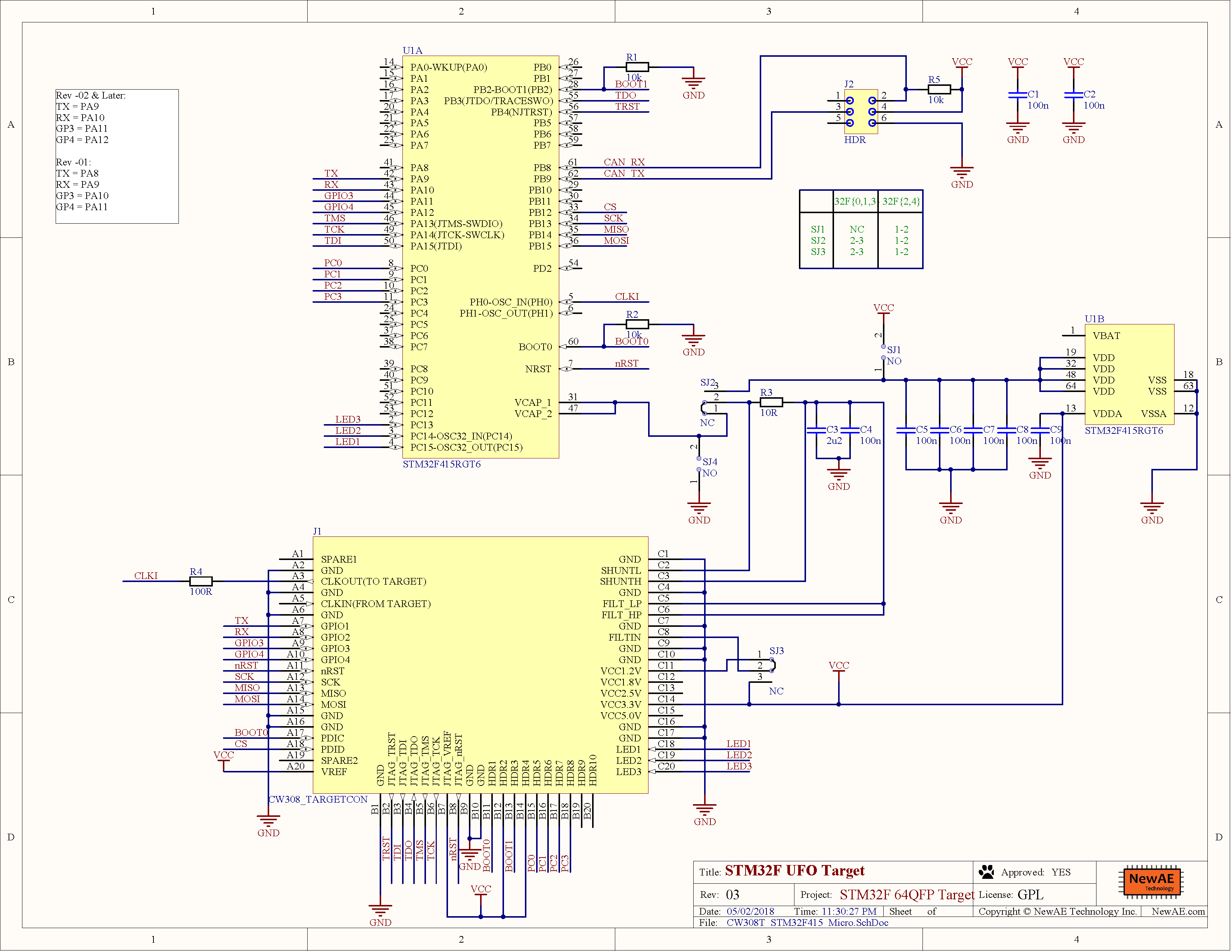
Rev -03 Schematic#
The current revision of the target is -03. The following shows this schematic:
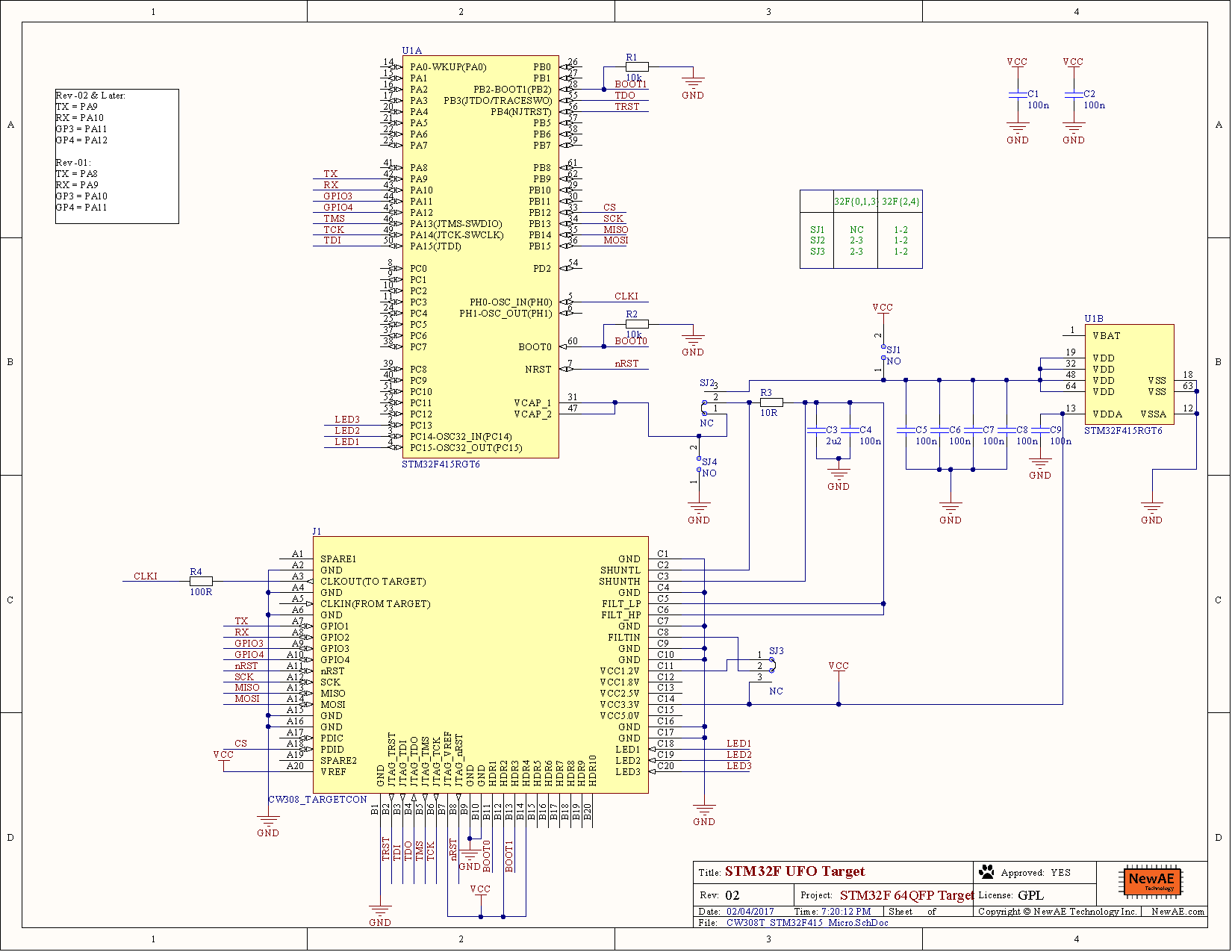
Rev -02 Schematic#
The original board sold was the -02 revision. The revision is part of
the part number, for example these boards will be marked STM32F-02. The
-02 revision also does not have the CAN connector:

Errata#
STM32 Parts Differences#
Due to part availability, some boards may come with slightly different microcontrollers (typically a larger internal flash and/or SRAM) which may have different hardware optimizations. This won’t affect most attacks, but may affect template attacks across devices. For example, a template generated for an STM32F303RCT7 may not work on an STM32F303RDT6 and vice versa.